
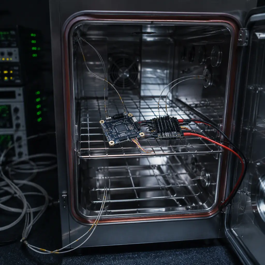
The gap between a component that passes its datasheet checks and a component that survives its mission is environmental exposure. A flight controller can pass every electrical test on the bench and still fail after 200 thermal cycles, when the coefficient-of-expansion mismatch between a BGA package and the PCB finally cracks a ball. An ESC can deliver its rated current at 25 °C and derate itself into a brownout at 55 °C. A telemetry module can pass its range test and then lose the link when vibration loosens the U.FL connector. Environmental qualification testing is the systematic exposure of hardware to the environments it will meet, before the airframe does it for you. The propulsion testing and validation guide covers the thrust-chain tests; this guide covers the environmental test methods from MIL-STD-810 and RTCA DO-160 that every UAV component buyer should understand.
MIL-STD-810 vs DO-160: which standard to specify
Two standards dominate UAV component environmental testing, and they answer different questions. MIL-STD-810 (now 810H) is a U.S. Department of Defense standard describing test methods for military equipment. It is method-oriented, letting the buyer tailor test levels to the platform. RTCA DO-160 (now DO-160G) is the airborne equipment standard used in civil aviation certification (including the EASA/FAA path for UAS). It is category-based, with defined severity levels chosen by the equipment's installation. For UAV components, the practical guidance:
| Aspect | MIL-STD-810H | RTCA DO-160G |
|---|---|---|
| Origin | Military equipment, U.S. DoD | Airborne equipment, civil aviation (RTCA/EUROCAE) |
| Structure | Method per environment (Method 501.7 high temp, 514.8 vibration…) | Sections per environment (Section 4 temperature, 8 vibration…), severity categories |
| Tailoring | Levels tailored by the buyer to the platform | Categories selected by installation class |
| Common UAV use | Defense, public safety, rugged commercial components | Certified aircraft equipment, UAS type certification programs |
| Test report value | Method + tailored levels + measured data | Category + pass/fail per section |
Most rugged commercial UAV components are tested to MIL-STD-810 methods with tailored levels; components intended for certified aircraft are tested to DO-160 categories. Both are only as meaningful as the tailoring. A "MIL-STD-810 tested" claim without the method, level and duration is marketing, not data. The certification and compliance guide explains how these test standards relate to the CE, FCC and export compliance stack.
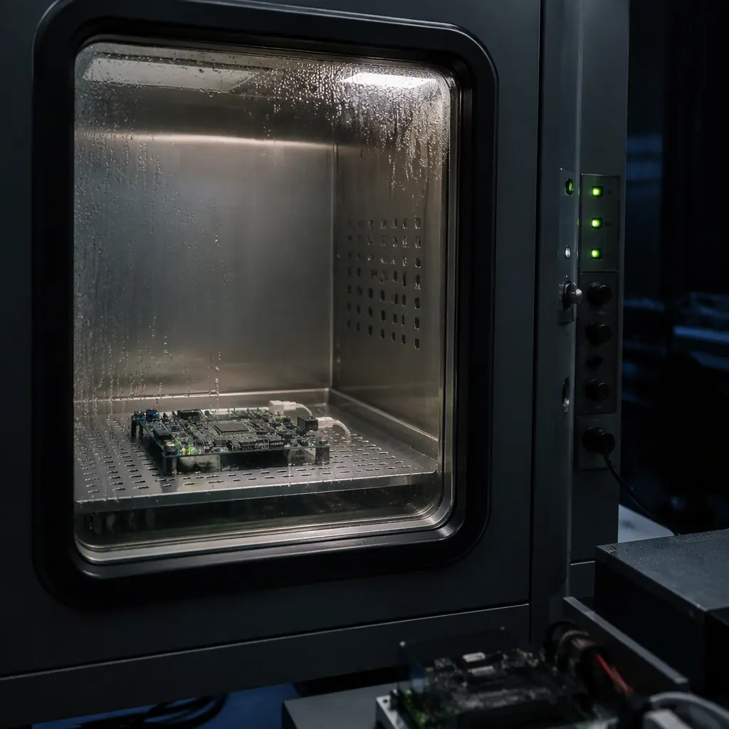 Thermal chamber
Temperature: the test that finds most solder failures
Temperature is the environment that UAV electronics cannot avoid: every flight crosses a thermal gradient, and the daily mission cycle (charge, fly, cool, charge again) is itself a thermal cycle. The two relevant test modes:
- High and low temperature operation and storage (MIL-STD-810 Methods 501.7 and 502.7; DO-160 Sections 4.5.1-4.5.2). The component operates (or survives) at defined temperature extremes for a soak duration. A typical industrial UAV specification is continuous operation -20 °C to +50 °C, with storage -40 °C to +70 °C. And the report must state whether the component was powered during the soak, because powered and unpowered behavior differ.
- Thermal cycling and thermal shock (MIL-STD-810 Method 503.7; DO-160 Section 5). The component is cycled between temperature extremes at a defined ramp rate and dwell time. Thermal cycling is the test that cracks BGA balls, delaminates PCB layers and separates conformal coating, failures that appear only after tens or hundreds of cycles. A credible UAV component qualification runs 50-200 cycles over a range of at least 70 °C.
What to check in the report: the actual temperature at the component (not the chamber set point), the ramp rate, the dwell time, whether the unit was powered, and the pass criteria, including for example, "no intermittent operation, no deviation beyond ±5% on supply current, no data errors on the serial bus." The thermal management guide covers the design side that keeps components inside these limits in flight.
Vibration and shock: what 500 flight hours does to a connector
Propeller-driven vibration is the defining mechanical environment of a UAV. A multirotor at hover excites its airframe at the rotor blade-pass frequency: typically 50-150 Hz for a 15-30 cm propeller at 5,000-12,000 RPM, plus broadband turbulence and motor harmonics. The test methods:
- Random vibration (MIL-STD-810 Method 514.8; DO-160 Section 8). The component is driven with a random vibration spectrum (PSD, power spectral density, in g²/Hz) across typically 10-2,000 Hz, for a defined duration per axis. UAV components are commonly qualified at 2-6 g RMS over 1-2 hours per axis, on all three axes. The failures this finds: connector fretting, solder fatigue, component lead cracking, fastener loosening.
- Resonance search and sine sweep. A low-level sine sweep identifies the component's resonant frequencies; the design goal is to keep the primary resonances away from the rotor excitation band, or to damp them. A component whose resonance sits at 60 Hz on a 6,000 RPM multirotor will vibrate itself apart.
- Shock (MIL-STD-810 Method 516.8; DO-160 Section 7). Half-sine or sawtooth pulses: typically 20-40 g, 11 ms for operational shock on a rugged UAV component, with 6 orientations. Shock finds brittle failures: ceramic capacitor cracking, crystal oscillator damage, solder joint fracture at the board edge.
The report must include the PSD profile (not just the g RMS), the duration per axis, the mounting method (because mounting changes the response), and functional checks during and after the test. A component that passes vibration with a foam mount and fails hard-mounted is a component that will fail in service, the report's mounting photos matter. The propeller balancing and vibration guide covers the airframe-side reduction of the same excitation.
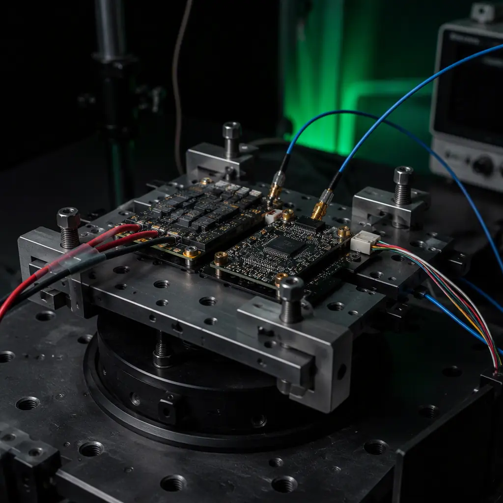 Vibration test rig
Humidity, salt fog, sand and dust: the corrosion and abrasion trio
Environmental qualification is not only about physics, it is about chemistry. Three test families cover the corrosive and abrasive world a UAV flies through:
- Humidity (MIL-STD-810 Method 507.6; DO-160 Section 6). The component is exposed to high relative humidity (typically 95% at 30-60 °C) in cycles that cause condensation. The failure mode is electrochemical: moisture + bias voltage + ionic contamination = dendritic growth and leakage currents. Condensation on powered electronics is the reason UAV avionics need conformal coating, the electronics manufacturing quality guide covers the IPC-A-610 and coating standards that make humidity test pass rates respectable.
- Salt fog (MIL-STD-810 Method 509.7). A 5% NaCl fog at 35 °C, typically 24-48 hours, accelerates corrosion of unprotected metals. It is the test for coastal operations, offshore inspection and maritime logistics UAVs. Bare aluminum, non-stainless fasteners and uncoated connectors fail fast; the report should state the exposure duration and the acceptance (no functional degradation, no red rust on critical surfaces).
- Sand and dust (MIL-STD-810 Method 510.7). Airborne dust (blowing dust, typically 10-150 µm particles) and blowing sand (150-850 µm) test seal integrity and abrasion resistance. For UAVs this is the desert and agricultural environment test, the same environment covered on the mission side by the agriculture components guide. Dust ingress into gimbal bearings, connectors and cooling intakes is a leading cause of field failure in arid regions.
The waterproofing and IP ratings guide connects these tests to the IP code. An IP67 rating is a separate verification (dust-tight + immersion) that complements, but does not replace, MIL-STD-810 corrosion testing.
Altitude and pressure: the derating nobody budgets for
Altitude testing (MIL-STD-810 Method 500.6; DO-160 Section 4.6) covers two distinct effects that UAV operations at 1,000-5,000 m altitude trigger:
- Reduced cooling. Air density at 3,000 m is about 70% of sea level, so convective cooling of ESCs, motors and batteries drops by roughly the same fraction. A propulsion system thermally validated at sea level can overheat at altitude under the same load, the reason the heavy-lift propulsion design guide insists on altitude-aware thermal margins.
- Reduced dielectric strength and pressure differentials. Lower pressure reduces the breakdown voltage of air (relevant for high-voltage power electronics) and creates pressure differentials across sealed enclosures, the venting problem covered in the waterproofing guide's pressure-equalizing vent section. A sealed payload at 4,000 m with no vent sees internal overpressure that can push moisture past gaskets on descent.
The report should state the tested altitude (or the chamber pressure in kPa), the powered or unpowered state, and the functional criteria: for example, "full throttle endurance at 3,000 m simulated altitude with no thermal derating beyond the specified curve."
How to read an environmental test report
An environmental test report is only as useful as its completeness, and UAV component reports vary from a single sentence ("temperature tested OK") to full data packages. The five checks that separate a real qualification from a checkbox:
- 1. Method and standard stated. "MIL-STD-810H Method 501.7, Procedure I (storage)" with the standard revision, not "tested to MIL-STD-810".
- 2. Tailored levels and durations. Temperature range, soak hours, cycle count, PSD profile, g RMS, duration per axis. A report without levels is a brochure.
- 3. Powered or unpowered. Whether the unit was operating during each phase. Powered testing is harder and more meaningful for electronics.
- 4. Functional pass criteria. What "pass" meant: measured current draw, data integrity, timing, output accuracy, not "no visible damage".
- 5. Sample count and serialization. How many units, from which batch, with serial numbers. One hand-picked unit is not a qualification.
For procurement, these checks belong in the RFP, the UAV component RFP guide shows how to write test clauses with defined verification, and the supplier evaluation checklist shows how to score the responses. Environmental test data is one of the clearest signals of a manufacturer that tests what it ships: a supplier that publishes full reports with serial numbers is a supplier that runs the tests.
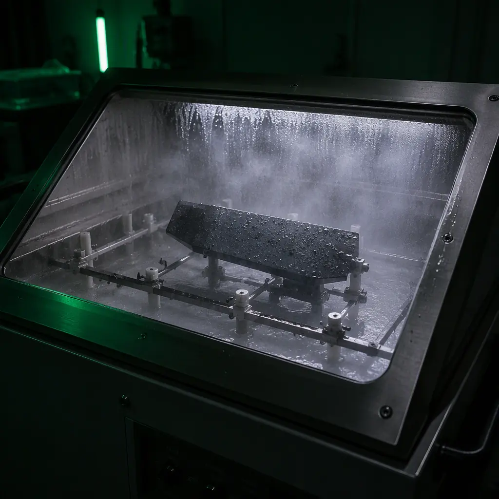 Salt fog chamber
Specifying environmental testing in procurement: the minimum clause
A workable environmental qualification clause for a UAV component purchase, covering the mission profile the buyer knows (operating region, flight altitude, coastal or desert exposure, flight hours per year):
- Temperature: continuous operation -20 °C to +50 °C, storage -40 °C to +70 °C, 100 thermal cycles over the operating range, powered during cycling, with measured supply current and no data errors.
- Vibration: random vibration 10-2,000 Hz, 4 g RMS, 1 hour per axis, three axes, hard-mounted, functional check at 0 dBm RF output stability and no connector discontinuities.
- Humidity: 95% RH at 40 °C, 10 cycles with condensation, powered, leakage current below the datasheet limit.
- Salt fog and dust: only if the operating environment requires them, coastal and desert missions respectively, 24-48 h salt fog, blowing dust per Method 510.7, acceptance = no functional degradation.
- Reporting: serial-numbered per-unit test reports with the standard, method, levels, durations, mounting photos, and functional data, delivered with the hardware.
The bottom line: environmental qualification is how a component buyer converts "it works on the bench" into "it works on the airframe, in the region, for the mission." The standards exist, the methods are documented, and the difference between suppliers is whether the test data exists and whether it is real. EMS Drone tests every critical component, flight controllers, ESCs, RF modules, with powered functional checks and thermal cycling as standard, and can supply MIL-STD-810-style environmental test data, vibration profiling and altitude testing for custom stacks. Send the operating environment and the mission profile, and we will return the test plan that matches it.
What environmental qualification actually costs, in absolute terms.
Test-house invoices are the smallest line. The costs that decide a qualification programme sit on either side of the chamber: making a unit that can survive it, and re-running the programme when a design changes late. The bands below are what a mid-size UAV avionics programme typically spends per qualification event, and the last column is the one buyers should use to budget.
| Cost item | Order of magnitude | What drives it | One-off or per design change |
|---|---|---|---|
| Accredited chamber time (thermal, vibration, humidity per MIL-STD-810H) | USD 12,000 - 35,000 per article | Number of methods, soak durations, mounting fixtures, whether testing is powered | Per design change |
| Qualification test plan and procedure authoring | USD 4,000 - 9,000 | Mission profile definition, derived levels, acceptance criteria | One-off, reusable if the profile does not move |
| Purpose-built vibration fixture and thermal harness | USD 3,000 - 8,000 | Airframe mounting resemblance, accelerometer placement, harness routing | One-off per mechanical envelope |
| Design hardening to reach the levels (stiffening, conformal coat, derating) | USD 8,000 - 40,000 | How far the first prototype missed, whether stiffening forces a tooling change | Per design change |
| Failure investigation and second article | USD 5,000 - 20,000 | Whether the first failure is a design fault or a fixture artefact | Contingency, but budget it as certain |
| Re-run after a firmware or mass change | 60 - 100% of the original chamber bill | The change touches power behaviour, mounting mass, or connector part numbers | Per change, and it is the line nobody budgets |
The line that gets underestimated is the last one. Teams budget the first campaign and treat the test report as an arrival, not a subscription. A connector part-number change alone can invalidate the vibration method because the failure mode being screened for is exactly the mass-and-contact interface that changed. Buyers who ask for the fixture drawings and the mounting photos in the report are the ones who can re-run cheaply later, because the expensive intellectual property in the programme is not the chamber time, it is the reproducible setup.
Which qualification obligations sit with the supplier and which with the operator.
Qualification failures are almost never a clean supplier fault or a clean operator fault. They sit on a boundary that nobody writes down. The split below is the one that holds up in practice for UAV component purchases.
| Item | Supplier obligation | Operator obligation |
|---|---|---|
| Definition of the operating environment | State the limits the design was qualified to, in standard, method and level | State the actual mission profile: region, altitude, coastal exposure, hours per year |
| Test level derivation | Derive test levels from the stated profile and show the derivation | Correct the profile when operations move to a different region or airframe |
| First-article qualification evidence | Deliver serial-numbered reports with methods, levels, durations, mounting photos and functional data | Read them, and reject reports that state a pass without the numbers |
| Change notification | Notify before any change that can affect a qualified characteristic, and state the requalification position | Decide whether to accept the delta or require a re-run, before the change ships |
| In-service environmental monitoring | Provide the counters and telemetry hooks that expose accumulated exposure | Track actual vibration, thermal cycles and salt exposure across the fleet |
| Firmware and configuration changes | Assess against the qualified configuration and declare when a firmware change triggers requalification | Do not push a configuration change that alters power behaviour without an updated test position |
| Repair and rework | Rework only to the qualified process, and requalify if the process changes | Do not accept field repairs that change mass distribution or sealing |
The clause that carries the most weight is the firmware one. A flight controller that passes thermal cycling at one set of power states does not automatically pass at another, and firmware controls which power states exist. If the agreement does not say who re-qualifies after a firmware change, the answer in practice is nobody, and the first sign is a thermal shutdown in a cold-weather deployment. The same logic applies to propeller hub changes and battery pack swaps: both alter the mass at the same interface the vibration method was designed around.
Two real builds, and the numbers that came out of qualification.
The point of quoting these is not the aircraft. It is that in both cases the qualification-relevant numbers were fixed by a design decision that looked like a performance decision at the time.
- Heavy-lift agricultural platform, 1600 mm coaxial airframe, 30 L payload, MTOW around 25 kg. The arm is a 30 mm carbon fibre tube with CNC aluminium motor mounts, and the landing gear holds the spray bar 350 mm clear of the ground. Two of those numbers are environmental qualifications in disguise. The 350 mm clearance is what keeps the spray bar out of dust and crop debris in the ground-effect zone, so the blowing-dust method is specified against a nozzle height rather than against the airframe. And the coaxial layout puts two motor masses on one 30 mm tube, which sets the vibration level at the arm root well above what a flat-eight layout of the same payload produces. A qualification programme that assumed a flat-eight spectrum would pass on the bench and fail at the arm root in service, because the bench fixture reproduced the frame, not the layout.
- VTOL LiDAR mapping platform, 120 min endurance, 5 kg payload. The payload sits in a belly pod that adds 0.8 kg and 12% parasitic drag, and the GPS antenna is isolated from the pod with 15 mm of foam. The pod is the qualification case study on this aircraft, and it cuts both ways. It is outside the pressure vessel and outside the thermal envelope of the fuselage, so its electronics see the full -20 to +50 degree swing with no cabin conditioning, and the foam isolation is a vibration measure that also becomes a thermal insulator. The number worth copying into a test plan is the 15 mm: it is a coupled decision, and it is not something a component datasheet can tell you is correct.
Both builds argue the same procurement point. The climate and vibration levels in a report are only meaningful together with the mounting arrangement they were measured on, so the fixture drawing and the mounting photos are part of the qualification evidence, not an appendix. Ask for them before the purchase order, because after the programme closes the setup is the one thing that costs money to reconstruct.
Clauses for an environmental qualification agreement.
Every number above converts into one sentence in a purchase agreement. These are the clauses that carry the qualification instead of leaving it to goodwill.
- Environment declaration: the supplier states the qualified envelope as standard, method and level for temperature, vibration, humidity, altitude and any contamination the design claims, and names the region and airframe the levels were derived for.
- Derivation on file: test levels are traceable to the operator mission profile, and the derivation is a deliverable, not a working note.
- Serial-numbered evidence: first-article reports include the mounting arrangement, accelerometer positions, functional measurements during exposure, and pass or fail against stated numeric acceptance criteria. A report that states only a pass is rejected.
- Fixture and mounting photography: delivered with the report, because the arrangement is what makes the result reproducible on a later article.
- Change notification with a requalification position: the supplier may not alter mass, mounting interface, connector part number, potting, or firmware power behaviour without notifying the buyer and stating which methods remain valid.
- Baseline as a deliverable: the as-built measurements from the first qualified article, vibration response and thermal performance both, are handed over. Without a baseline the operator cannot tell a later drift from a later damage.
- Requalification cost sharing: a change instigated by the operator carries the re-run cost, a change instigated by the supplier does not, and a change the supplier failed to notify is treated as out of qualification.
- Non-sampleable acceptance: whole-unit methods that cannot be sampled from a batch are witnessed per serial number or per lot with the witnessing right named in the agreement.
The agreement is short compared with the engineering behind it, which is why it is worth writing before the first prototype reaches a chamber rather than after. If you are specifying a component and want the levels derived from an actual mission profile, see how we run qualification and validation, or send the operating environment for a test plan.
What a qualification programme costs when the levels move
The band that decides a defence or certification programme is rarely the first campaign. It is the second one, run because a mount changed, a connector was substituted or a firmware release altered power behaviour after the first report was signed. The table prices the individual activities so a programme manager can see which of them are one-off engineering work and which of them repeat every time the configuration moves. The bands are what we see on UAV avionics and airframe programmes in the 5 to 25 kg class.
| Activity | Typical band (USD) | What actually drives the number | Repeats when |
|---|---|---|---|
| Derived test levels from the mission profile | 3,500 to 8,000 | Whether measured flight data exists; deriving levels from a MIL-STD-810H default table instead of from recorded vibration is cheaper and argues less well in an audit | Mission profile change, or a change of mounting location on the airframe |
| Vibration fixture design and build | 4,000 to 11,000 | Whether the fixture has to reproduce the real mounting stiffness; a rigid plate is cheap and screens nothing, a representative bracket set is a machined part with its own modal check | Any change to the mounting interface or to the mass of the unit |
| Accredited chamber time, thermal and altitude | 9,000 to 30,000 | Number of methods, soak dwell, whether the unit is powered and loaded, and whether test slots are booked on a multi-week lead time at an accredited facility | Any change that touches thermal mass, dissipation or enclosure |
| Powered test harness and instrumentation | 2,500 to 6,000 | Number of monitored channels, whether telemetry has to run through the chamber wall, and whether the harness is qualified for the same temperature range as the unit | Connector or pinout change |
| Design change to reach the level | 6,000 to 45,000 | Whether the miss is a bracket resonance or a component rating; the first is a drawing change, the second is a resourcing exercise across a bill of materials | Once per miss, and the second miss is usually more expensive than the first |
| Second article and failure investigation | 4,000 to 18,000 | Whether the first failure is real or a fixture artefact; proving it was the fixture costs a full re-run with a modified setup | Per failure event, budget one as certain |
| Re-run after a late design change | 55 to 100 percent of the first campaign | A connector substitution can invalidate the vibration method because the screened failure mode is the mass-and-contact interface that changed | Every late change, and this is the line that is never in the first budget |
| Report package and witness documentation | 1,500 to 4,000 | Whether a customer witness is required at each method, and whether photographic evidence of the mounting arrangement is captured during the run | Per campaign, but the photographic set is reusable if the setup is unchanged |
Read the recurrence column before the cost column. A programme that spends 40,000 on the first campaign and then re-runs it twice at 30,000 per re-run has spent more on repetition than on the original qualification. The two decisions that suppress the repetition cost are made at the start: specify the mounting arrangement as a controlled interface rather than as "as installed", and freeze the connector and enclosure part numbers before the first chamber slot is booked. Both are cheap in week one and expensive in month nine.
Who holds the qualification obligation, supplier or buyer
Qualification failures are rarely a clean supplier fault or a clean customer fault. They land on a boundary that nobody wrote into the purchase order, and the argument afterwards is about that boundary rather than about the failure. The split below is how we write it on component supply programmes where the customer owns the aircraft-level integration.
| Scope | Component supplier owns | Airframe integrator owns |
|---|---|---|
| Declared qualification envelope | Publishes the standard, method and level each claim was demonstrated against, with the report reference | Declares the real mission profile: operating region, altitude band, coastal or desert exposure, annual flight hours |
| Testing to the declared level | Provides the report, the fixture description and the mounting photographs for every method claimed | Checks that the tested mounting arrangement matches the intended installation before accepting the report |
| Derived levels for the installed location | States the levels the unit was tested at, not the levels of the aircraft | Derives aircraft-level levels from flight data and confirms the unit is within its demonstrated envelope at its actual mounting point |
| Configuration control | Notifies of any change to enclosure, connector, potting compound, component rating or firmware that affects power or thermal behaviour | Treats a notified change as a design change and re-qualifies to the same evidence standard; no notification, no fitment |
| Witness and access | Allows a customer witness at the chamber for the agreed methods, on reasonable notice | Attends or sends a representative, and records the mounting arrangement at the time of the run |
| Failure analysis | Returns the failed article intact with the test log and the as-built configuration record | Preserves the article and the harness before any rework, so the failure mode is still observable |
| Post-change evidence | Supplies the delta between the original and changed configuration, in writing | Re-runs only the methods the delta actually touches, and records the reasoning for the reduced scope |
The row that gets tested in practice is configuration control, because it is the one that fails silently. A potting compound substitution that keeps the same part number on the drawing, or a firmware release that raises peak current during a transition, changes the thermal and vibration response without anyone intending a design change. The engineering answer is to make the notification obligation explicit and to make the integrator's response automatic rather than discretionary: a notified change triggers a documented re-qualification decision, not a conversation. That is the difference between a programme that can defend its evidence file three years later and one that cannot reconstruct what was tested.
Two reference builds and which environmental decision mattered on each
Neither platform below was qualified as an exercise. In both, one environmental decision made early set the cost of every campaign that followed, and in both cases it looked like a performance or packaging decision at the time it was taken.
Heavy-lift agricultural X8, 25 kg MTOW, 30 L tank. Eight 80 A 12S ESCs on a 400 A distribution board, drawing 3,000 to 4,000 W during a spray pass at roughly 80 A on a 44.4 V bus. At that dissipation the ESC bay is the thermal case study on the aircraft, and the decision that settled the qualification was airflow rather than rating: the ESCs sit in the propeller wash, which gives enormous convective headroom in flight and none at all during a stationary pre-flight check on a hot apron. The thermal method therefore has to be specified with a powered, stationary dwell at maximum ambient, which is a harsher and more expensive test than the in-flight condition that the cooling design was optimised for. The full architecture, including the cooling airflow assumptions that set the ESC placement, is documented in the heavy-lift agriculture reference build.
Long-endurance VTOL mapping platform, 5 kg payload, 120 minutes. An 888 Wh 6S8P Li-Ion pack delivering roughly 85 W in cruise, with the mapping payload in a belly pod. The pod is outside the fuselage thermal envelope, so its electronics see the full ambient swing with no cabin conditioning, and every degree of that swing is a qualification level rather than a design margin. The decision that mattered was pod isolation: the same foam that attenuates vibration also insulates, so the vibration fix and the thermal exposure moved in opposite directions and the pod became the single hardest article on the aircraft to qualify. The energy budget and the pod arrangement are published in the LiDAR mapping platform reference build.
The transferable point is that both articles were qualified on an installed configuration rather than as standalone units, and both had at least one coupled decision that a datasheet could not have settled. If the programme is at the specification stage, the RFQ component specification guide shows how to state the mounting and envelope as controlled interfaces, and the pre-shipment inspection guide covers the evidence to collect before the article leaves the supplier.
Acceptance evidence: what has to be in the report package
A report that states "passed" without the conditions is a claim, not evidence. The matrix below is the package structure we ask suppliers to populate, and the right-hand column is where most packages thin out. Rows marked as not samplable per unit cannot be turned into a pass or fail statement on a delivered article no matter how the supplier words the certificate.
| Item | Acceptance form | Samplable per unit |
|---|---|---|
| Derived levels | Level table with the derivation source, either flight data reference or standard table clause | No, this is a design-level property |
| Vibration response | Accelerometer traces at the mounting point, before and after the dwell, with the fixture shown | No, on a sample basis at best |
| Thermal functional check | Functional performance at the cold and hot extremes while powered and loaded, not just survival | Yes, per configuration |
| Altitude derating | Performance curve against pressure altitude, with the derating knee marked | Yes, per configuration |
| Immersion and salt fog | Post-exposure insulation resistance and visual record under magnification | Sample only, and destructive in some methods |
| Configuration record | As-built part numbers for enclosure, potting, connectors and firmware, matched to the report | Yes, per unit, and this is the row that makes the report traceable |
| Mounting photographs | Dated images of the article installed in the fixture, taken before and after each method | Yes, per campaign, reusable if the setup is unchanged |
The configuration record is the item worth arguing for. Reports age badly when the as-built list is missing, because a subscriber cannot establish whether the article in front of them is the one that was tested. A report with a complete configuration record survives a part substitution; one without it becomes a document that has to be re-earned. If the platform has already been through one campaign and the levels moved, the environmental monitoring component guide covers the sensor side of the same problem, and the electronics manufacturing quality guide covers the process evidence that a test-house report does not contain.
When the platform is defined and the question is which articles can be delivered with qualification evidence attached, our airframe and structures capability page lists the structural classes we build, and a test plan can be requested through the quotation form with the mission profile attached.
Explore testing & validation Back to Blog
EMS Drone manufactures qualification-tested avionics under one roof, from component sourcing through production test. If you are specifying for a build, see the full capability set and the tolerances we hold.
Continue Reading
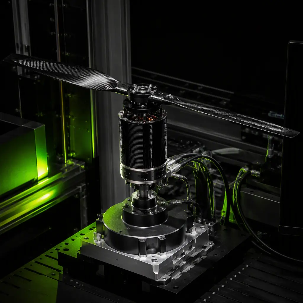
UAV Propulsion Testing and Validation
The thrust-chain test philosophy that pairs with environmental qualification.
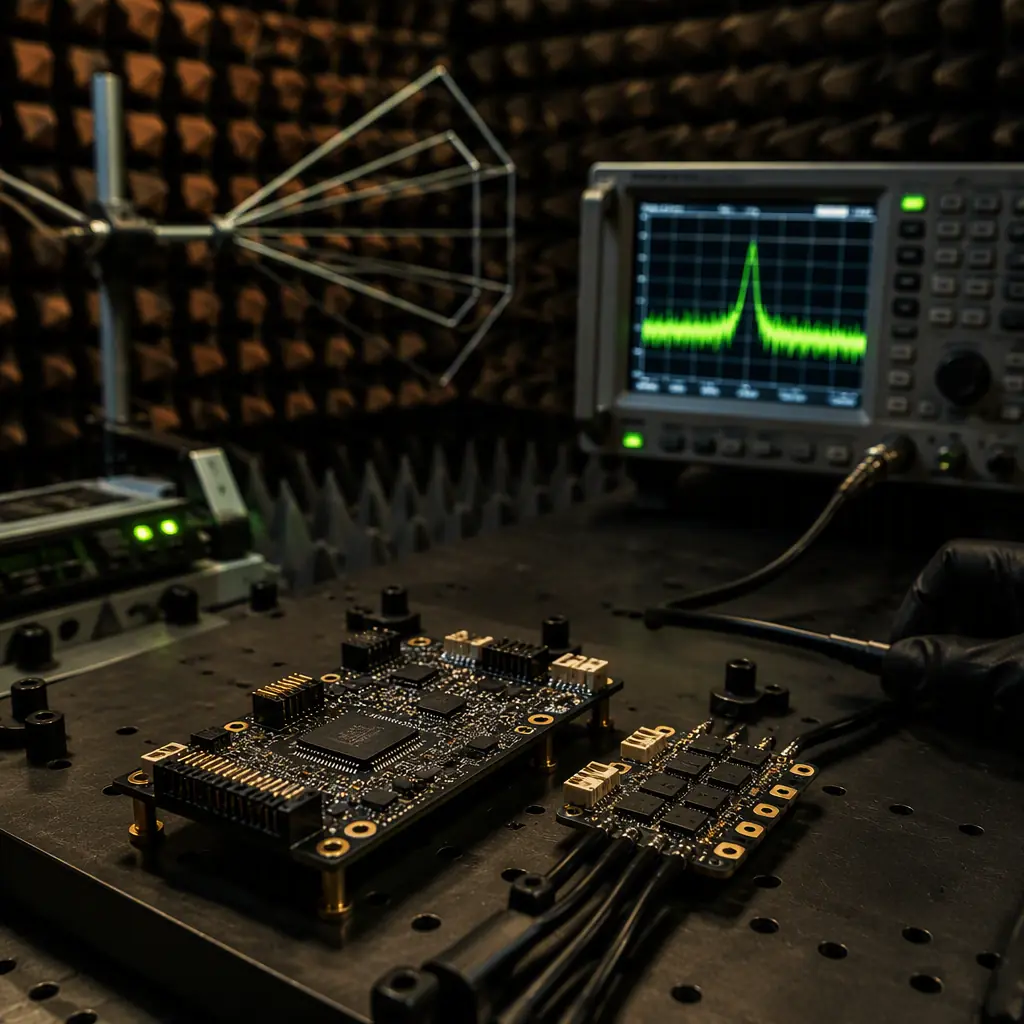
UAV Avionics EMC and EMI
The electromagnetic test methods that run alongside environmental qualification.
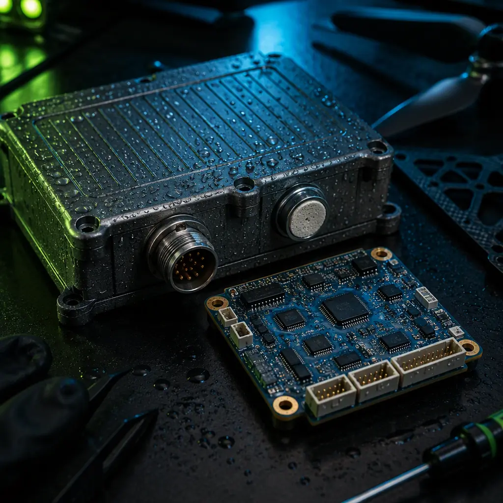
UAV Waterproofing and IP Ratings
How IP ingress verification complements MIL-STD-810 corrosion testing.
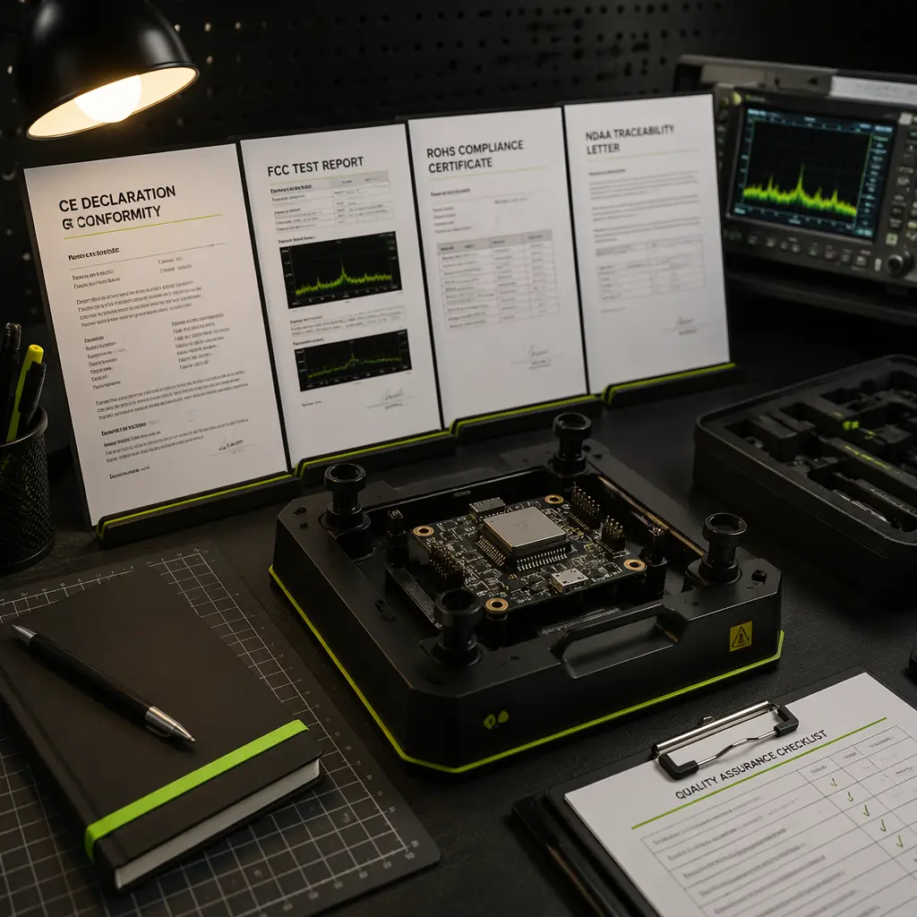
UAV Certification and Compliance
Where test standards fit in the CE, FCC and export compliance stack.
Writing a UAV Component RFP
How to write the environmental test clause into the specification and acceptance criteria.