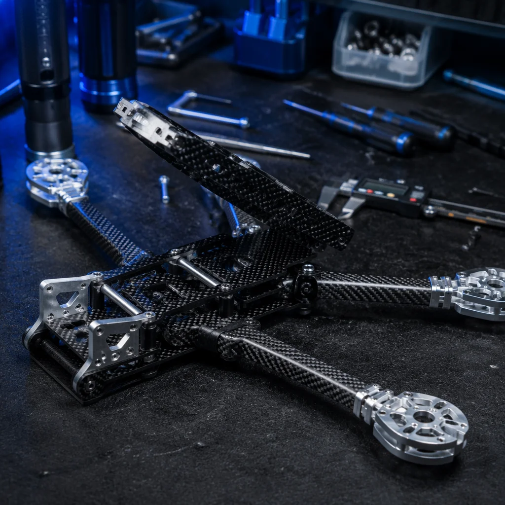
Conceptual UAV airframe structure with carbon fiber arms and center plates Concept illustration
Capabilities / Airframe

Airframes & Structures

The physical skeleton: frame geometry, material selection, structural load paths and mechanical integration for every configuration from micro quads to heavy-lift industrial platforms.

RoleSkeleton of the UAV
ConfigurationsQuad / Hexa / Octo / Fixed-Wing / VTOL
MaterialsCarbon Fiber / Aluminum / Nylon / Composite
DepthFrame Kit → Complete Structure
Overview

The airframe carries every gram of payload and absorbs every Newton of stress.

The airframe is more than a set of plates and arms — it is the structure that defines motor geometry, vibration transmission, crash survivability and thermal management. Getting the frame right means matching wheelbase, arm thickness, plate layup and fastener spec to the aircraft's all-up weight, flight envelope and operating environment. A well-designed airframe adds no unnecessary mass while delivering the stiffness and durability the mission demands.

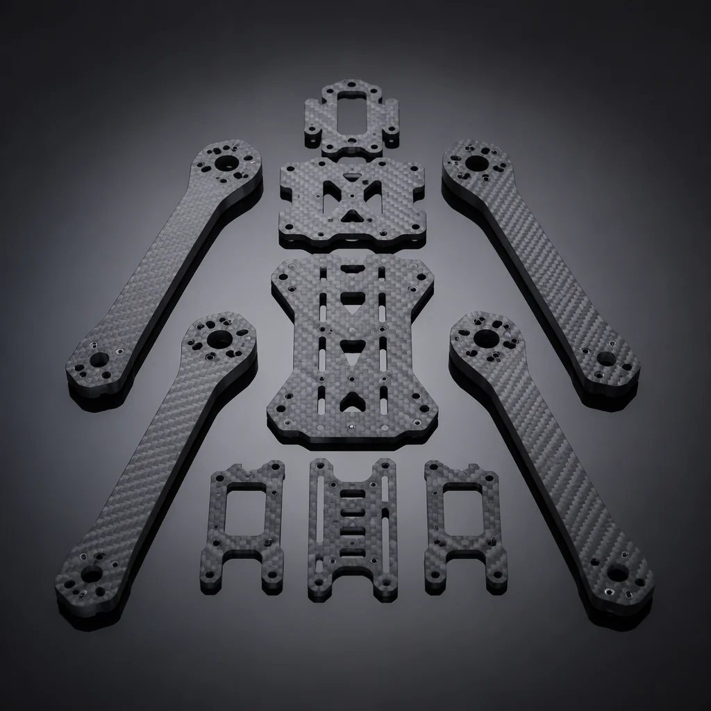
Carbon fiber quadcopter frame with center plates, tubular arms, and motor mounting brackets in exploded view Concept illustration
Frame Platforms

Four platform categories, from agile inspection to heavy cargo.

Each configuration has a distinct structural logic — motor count, arm geometry, mounting interface and load distribution change with the platform.

Quadcopter

Lightweight agility

The most common multi-rotor layout: four motors on two orthogonal arm axes. Frame weight ranges from under 30 g for micro 3-inch builds to 800 g and above for 15-inch-plus heavy-lift platforms. Center-plate stack mounting (30.5x30.5 mm or 20x20 mm) holds the flight controller and ESC stack. Arms are typically removable — clamped or bolted — for field repair. Dead-cat and stretched-X geometries push the front arms forward to keep propellers out of camera view, a critical consideration for cinematography and inspection builds where the camera faces forward.

  • 3–15+ inch
  • 30.5mm stack
  • Dead-cat geometry
  • Removable arms
  • Sub-30g micro
Hexacopter

Redundancy and lift capacity

Six motors in a symmetric arrangement provide motor-out redundancy — the aircraft can maintain controlled flight and land safely after a single motor or ESC failure. This makes hexacopters the default choice for applications where payload value, flight-over-people risk or operational cost of a crash demands redundancy. Typical wheelbases range from 550 mm to 1200 mm, with payload capacities from 2 kg to 25 kg. Yaw authority is stronger than equivalent quadcopters due to the additional counter-rotating motor pairs, improving heading-hold performance in gusty conditions.

  • Motor-out safety
  • 550–1200mm
  • 2–25 kg payload
  • Strong yaw
  • Coaxial option
Fixed-Wing

Endurance through aerodynamic efficiency

Wing, fuselage and empennage structures designed for lift-generated flight rather than thrust-only hover. Fixed-wing airframes achieve 3x to 10x the endurance of an equivalent-weight multi-rotor on the same battery capacity. Construction typically uses molded EPO or EPP foam with carbon fiber spars, or fully composite layups for larger platforms. Wingspan ranges from 600 mm hand-launch mapping platforms to 3 m-plus long-endurance survey aircraft. Motor mount, servo pockets and payload bay geometry are the critical structural integration points.

  • EPO / EPP foam
  • Carbon spars
  • 600mm–3m span
  • Payload bay
  • Belly or rail launch
Custom Geometry

Application-specific structures

When standard frame kits do not fit the mission — unusual motor count (tricopter, octocopter, X8 coaxial), non-planar arm geometry, folding mechanisms for tube-launched platforms, or airframes that integrate payload housings as structural elements. We work from load requirements, motor layout and packaging constraints to specify plate profiles, arm sections, fastener arrays and material stack-ups. Custom geometry also covers VTOL tilt-rotor and tailsitter structures where the airframe must handle both hover and forward-flight load cases without compromising either flight regime.

  • Tricopter / X8
  • Folding arms
  • Tube-launch
  • VTOL hybrid
  • Structural payload
Materials & Construction

Every gram of structure must earn its place in the air.

Material choice determines stiffness-to-weight ratio, vibration damping, fatigue life and manufacturing cost — all in tension with each other.

Primary Structure

Carbon fiber twill — 3K, 6K, 12K

The default material for multi-rotor arms and center plates. Twill-weave carbon fiber sheet (typically 1.5 mm to 6 mm thick for arms, 1.0 mm to 3.0 mm for plates) delivers exceptional stiffness-to-weight ratio — a 250 mm arm weighing under 40 g can support a 1.5 kg thrust motor. 3K weave offers a fine cosmetic finish; 6K and 12K provide higher strength at the cost of slightly coarser surface. Edge finishing (chamfered and sealed) prevents delamination in humid or high-vibration environments. Pure carbon fiber is electrically conductive — frame grounding and ESC isolation must be considered during design to prevent short circuits through the frame.

Metallic Components

CNC-machined 7075 aluminum

Motor mounts, arm clamps, landing gear brackets and folding mechanisms where carbon fiber cannot provide the necessary thread strength or complex 3D geometry. 7075-T6 aluminum offers tensile strength comparable to mild steel at one-third the weight — yield strength around 500 MPa versus 6061-T6 at 275 MPa. Anodized finishes (Type II for general use, Type III hard anodize for wear surfaces) protect against corrosion. Threaded inserts (stainless steel helicoils, M2.5, M3, M4) are press-fitted into aluminum bosses to prevent galling under repeated assembly cycles and maintain consistent clamp load over hundreds of maintenance cycles.

Non-Structural & Damping

Injection-molded nylon and TPU

Landing gear skids, antenna mounts, GPS mast bases, vibration isolation grommets and protective enclosures use glass-fiber-reinforced nylon (PA6-GF30) for rigid parts and TPU (thermoplastic polyurethane) for flexible, impact-absorbing components. Nylon parts are lightweight, chemical-resistant and cost-effective in production volumes. TPU vibration dampers with Shore hardness A40–A60 isolate the IMU from motor-frequency vibration — a critical detail that directly affects flight controller attitude estimation quality. Dampers are selected to match the dominant motor vibration frequency, typically 100–300 Hz for multi-rotor applications.

Sizing Guide

Wheelbase, motor class, propeller and payload — the four linked dimensions.

Selecting the right frame starts with the payload requirement and works outward. This table provides a reference for multi-rotor sizing from micro to industrial scale.

Wheelbase (diagonal)Frame size from motor center to opposite motor center. Defines the maximum propeller diameter and, together with arm geometry, the aircraft footprint. Larger wheelbases improve pitch and roll stability at the cost of agility and transportability. Common benchmarks: 180–250 mm for 3–5 inch micro/racing; 450–650 mm for 10–15 inch mid-range; 800–1200 mm for 18–22 inch heavy-lift; 1200+ mm for industrial platforms with 24-inch-plus propellers and payload capacities exceeding 20 kg.
Motor size (stator)Stator diameter and height correlate directly with torque output and sustainable current draw. 2204–2207 for 3–5 inch props; 2806–2812 for 7–10 inch; 40xx–50xx for 12–18 inch; 60xx–80xx and above for 20-inch-plus heavy-lift platforms. Taller stators (e.g. 2814 vs 2808) produce more torque at the same diameter, useful for low-RPM efficiency on larger propellers. The motor must physically fit the arm's mounting pattern — M2 screws on 16x16 mm for micro, M3 on 19x19 mm for mid-range, M4 on 25x25 mm or larger for industrial motors.
Propeller max diameterRoughly 40–50% of wheelbase for a quad — a 250 mm frame comfortably runs 5-inch props; a 650 mm frame handles 13–15 inch. Tip clearance between adjacent propeller discs should be no less than 10 mm to avoid blade interaction and acoustic inefficiency. Coaxial configurations (X8) halve the effective propeller area per motor but double the disc loading; prop sizing for coaxials should account for the 10–20% efficiency loss of the lower propeller operating in the upper propeller's downwash.
Payload estimateAs a rule of thumb for multi-rotors: payload capacity is approximately 20–35% of all-up weight for a well-tuned power system. A 5 kg AUW quad can carry roughly 1.0–1.7 kg of payload. Hexacopters can push toward 35–40% at the cost of endurance due to the additional motor and ESC mass. Fixed-wing platforms invert the relationship — the airframe is the smaller fraction of AUW and payload can be 40–60% of takeoff weight, which is why mapping and cargo delivery favor winged configurations for payload-heavy missions.
Arm thickness & width3 mm carbon for up to 5-inch; 4–5 mm for 7–10 inch; 6 mm hollow or 8 mm-plus solid carbon tube for 12-inch and above. Arm width should be at least 3x the motor mount bolt spacing to distribute bending loads into the center plate without stress concentration. Tubular arms (round carbon tube) offer superior torsional stiffness per gram compared to flat plate arms of the same cross-sectional area, and their circular profile presents the same bending stiffness regardless of thrust vector direction.
Integration Notes

Structural integration is where the airframe meets every other system.

These are the key structural interface checks we run for every build. Getting them right at the design stage avoids mechanical rework after assembly.

Stack mounting & vibration isolation

Flight controller and ESC stack mounting must provide both mechanical security and vibration decoupling. Soft-mount grommets (silicone or TPU, Shore A40–60) reduce motor-frequency vibration transmission to the IMU. Stack screw torque should be consistent — typically 0.4–0.6 N-m for M3 nylon standoffs. Over-tightening compresses the damping material and defeats isolation. On larger airframes, a separated IMU module mounted on a dedicated vibration-damped plate further improves attitude estimation accuracy by mechanically decoupling the sensor from frame resonance modes.

Power distribution & wiring routing

High-current paths (battery leads, ESC power wires) should run along arm channels or be secured to frame surfaces with cable ties through dedicated routing holes. Avoid routing power wires parallel to and directly adjacent to compass or GPS cabling — the magnetic field from 30 A-plus DC currents can produce compass errors of several degrees. Center-plate cutouts for XT60/XT90 connectors and capacitor banks should include strain relief features to prevent solder joint fatigue under vibration. Wire gauge must scale with current: 14–16 AWG for 30–60 A ESCs, 12 AWG for main battery leads above 60 A, and 10 AWG for 100 A-plus heavy-lift power systems.

Landing gear & payload hardpoints

Landing gear attachment must handle a minimum 3x aircraft weight in vertical impact — simulating a hard landing — without transferring load into the center plates or avionics stack. Payload rails or quick-release plates should be positioned close to the aircraft center of mass to minimize pitch and roll trim changes when payload is attached. Hardpoint locations in carbon plates should be reinforced with aluminum standoffs or additional carbon doublers to prevent local delamination under repeated load cycling. For retractable landing gear, the actuator mechanism must include end-stop limit switches and a manual override release in case of servo failure.

Environmental protection & corrosion

For operations in rain, coastal salt spray or agricultural chemical exposure: conformal-coated electronics in enclosed center-section bays with drain holes to prevent water accumulation; stainless steel (A2/A4) fasteners throughout to prevent galvanic corrosion between carbon fiber and standard steel hardware — carbon fiber is cathodic to most metals and will accelerate corrosion of untreated steel fasteners; sealed bearing cartridges in motor mounts; and anti-corrosion treatment on aluminum components. Carbon fiber in direct contact with aluminum requires a barrier layer — typically a thin G10 or glass-fiber isolator — to prevent galvanic corrosion at the dissimilar-material interface.

Related Capabilities

The airframe connects to power, control and payload.

Structural decisions ripple into every other subsystem. These are the most tightly coupled layers.

Flight Control

Stack sizing and sensor placement

Frame stack dimensions, vibration isolation strategy and IMU placement must be coordinated with the flight controller selection. The airframe defines where and how the FC reads the world — mounting location and isolation quality directly affect attitude estimation accuracy.

Flight Control
ESC & Power

Power path and thermal management

Arm channels, center-plate cutouts and cooling airflow paths are designed around the power system layout. ESC placement on the arms or in the center stack affects both weight distribution and component cooling — a decision that must be made at the frame design stage.

ESC & Power
Start With the Structure

Bring the payload class and the operating environment.

Tell us the aircraft configuration, target payload weight, operating conditions and any special structural requirements. We will map the frame platform, material specification and mechanical integration plan to your build.