 Concept illustration
Heavy-lift agricultural spraying platform
An architecture reference for an eight-rotor, 30-liter liquid-payload multirotor platform. This document walks through the component stack, the engineering rationale behind each subsystem selection, and the integration lessons learned during ground-up configuration of a heavy-lift agricultural UAV.
Platform overview
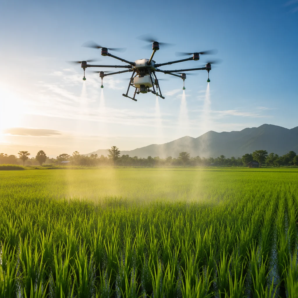
This reference architecture describes an X8 coaxial octocopter configuration — four arms, each carrying a coaxial motor pair — designed for sustained low-altitude agricultural spraying operations. The aircraft lifts a 30-liter liquid payload with a maximum take-off weight (MTOW) of 25 kg, providing approximately 12 to 15 minutes of active spray endurance per tank fill.
 Concept illustration
The mission profile assumes repeated short-duration sorties: take-off from a field-adjacent staging point, a low-altitude grid pass at 4 to 6 meters above crop at speeds of 5 to 8 m/s, return-to-land for tank refill and battery swap, then relaunch. This operating rhythm places distinct demands on the powertrain — sustained high current draw during the spray pass, followed by a brief thermal soak during turnaround, repeated across a full operational day.
Unlike an inspection or mapping aircraft that cruises at partial throttle, an agricultural sprayer spends the majority of its flight at high throttle settings with a near-constant liquid mass that decreases as the tank empties. This changing center of gravity, combined with the aerodynamic disturbance from rotor downwash interacting with crop canopy, makes flight controller tuning and vibration management central engineering concerns.
Subsystem Selection
Component architecture
Each subsystem was evaluated against the platform's specific demands: high thrust-to-weight ratio at low altitude, tolerance for particulate and moisture ingress, and electrical architecture that supports sustained high-current operation across eight propulsion channels plus an independent spray pump circuit.
Flight controller & navigation
A Cube Orange+ running ArduPilot was selected as the primary flight controller, paired with a Here3 RTK GNSS module for centimeter-level positioning accuracy. The decision was driven by three factors: the controller's triple-redundant IMU architecture provides the vibration tolerance needed for a large coaxial octocopter; ArduPilot's built-in sprayer control logic supports variable-rate flow control tied to ground speed; and the dual CAN bus ports enable direct connection to CAN-protocol ESCs without an intermediate signal converter.
The RTK base station is configured as a local reference — a tripod-mounted unit deployed at the field edge — eliminating dependency on NTRIP corrections in areas with unreliable cellular coverage. Terrain-following is handled through a downward-facing lidar rangefinder (LightWare SF11/C) interfaced over I2C, providing 0 to 100 meter range with a 100 Hz update rate.
ESC & motor configuration
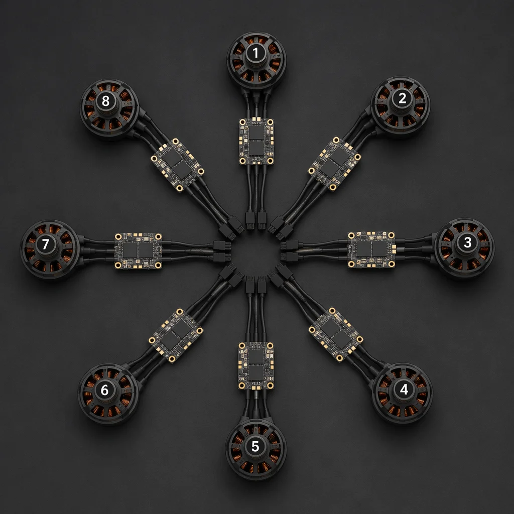
The propulsion system uses eight Hobbywing XRotor 80A 12S ESCs communicating over CAN bus with full telemetry feedback — per-channel RPM, current draw, MOSFET temperature, and error flags. CAN was chosen over PWM or DShot for this application because the telemetry data enables proactive detection of a failing ESC before it manifests as in-flight instability, a critical consideration on a single-point-of-failure octocopter platform.
 Concept illustration
Motors are 100KV outrunners wound for 12S operation, each driving a 30-inch carbon-fiber folding propeller. The low KV rating matches the large propeller diameter — 30-inch props on a 100KV motor at 12S (approximately 44.4 V nominal) produce a theoretical no-load RPM of roughly 4,440, with loaded RPM settling into the 3,200 to 3,600 range where these props develop optimal thrust efficiency. The coaxial arrangement recovers approximately 15 to 18 percent more thrust per arm compared to a flat octocopter layout at the same wheelbase, at the cost of slightly reduced efficiency on the lower propeller due to inflow interference from the upper rotor.
Power distribution & energy storage
The power architecture centers on a 400-amp-rated power distribution board (PDB) with 4-ounce copper traces on all high-current paths. Input is from dual 6S 22,000 mAh LiPo packs wired in series for 12S nominal (44.4 V), connected through XT90-S anti-spark connectors. The PDB provides eight dedicated ESC power pads plus an isolated 12 V regulated output for the spray pump controller, preventing pump motor noise from coupling back onto the avionics power rail.
A dual-redundant BEC configuration supplies regulated 5.3 V to the flight controller and companion electronics. The primary BEC draws from the main battery bus; a secondary independent BEC powered by a small 2S buffer battery provides fallback power to the flight controller and GNSS receiver, ensuring controlled return-to-launch capability in the event of a main power system failure.
Airframe & structural design
The airframe is a 1,600 mm wheelbase folding octocopter platform constructed from carbon-fiber tube arms (30 mm diameter) with CNC-machined aluminum motor mounts and a central hub assembly. The hub incorporates an IP54-rated sealed electronics bay with a breather valve to equalize pressure without admitting moisture or agricultural chemical mist. Arm attachment uses a dual-pin locking mechanism that folds for transport without disconnecting motor wiring — a practical necessity for field operations where the aircraft moves between paddies on a utility vehicle.
The 30-liter spray tank mounts to the underside of the hub via four vibration-dampened quick-release brackets with tool-less attachment. Tank positioning was modeled to place the liquid payload center of mass directly beneath the aircraft center of thrust, minimizing pitch and roll trim changes as the tank empties. The landing gear is a tall-profile skid design providing 350 mm of ground clearance — necessary to accommodate the spray boom when the aircraft is loaded and sitting on uneven terrain.
Spray system integration
The liquid delivery system comprises a centrifugal pump driven by a dedicated brushless motor controller, a 4-nozzle spray boom spanning 1,800 mm, and an inline electromagnetic flow rate sensor that feeds actual discharge data back to the flight controller. The pump controller accepts a PWM command signal from the flight controller auxiliary output, scaled against ground speed from the GNSS receiver to maintain a constant application rate per hectare regardless of aircraft speed.
 Concept illustration
Nozzle selection — hollow-cone ceramic tips with 1.0 mm orifice — was determined by the target droplet size range of 120 to 180 microns, balancing coverage uniformity against drift risk. The flow rate sensor provides closed-loop verification: if actual flow deviates beyond a configurable threshold from the commanded rate, the flight controller logs a warning and can trigger an automatic return-to-land. Power for the pump system runs on an isolated circuit from the main PDB, with a dedicated 30 A fuse and LC filter to suppress conducted EMI back onto the avionics bus.
Design Rationale
Key engineering decisions & trade-offs
Several architectural decisions involved trade-offs between competing priorities. These are documented here because they represent recurring judgment calls in heavy-lift multirotor design that apply beyond this specific reference platform.
Coaxial X8 vs. flat octocopter
The coaxial configuration reduces the wheelbase requirement by approximately 30 percent for a given propeller diameter — a 1,600 mm coaxial frame carries eight 30-inch props, whereas a flat octocopter would require a wheelbase exceeding 2,100 mm to clear the same prop arc. The trade-off is propeller efficiency: the lower rotor on each arm operates in the upper rotor's induced downwash, losing roughly 8 to 12 percent aerodynamic efficiency. For an agricultural platform where compact footprint for field transport outweighs the endurance penalty of coaxial losses, the X8 configuration is the pragmatic choice.
CAN ESC protocol over DShot or PWM
DShot offers simpler wiring and lower latency, but provides no telemetry feedback — the flight controller knows what command was sent but not what the ESC actually delivered. CAN protocol ESCs report per-channel current, temperature, and RPM at 10 Hz or faster. On an eight-motor platform where a single failing ESC can precipitate a crash, the diagnostic value of per-channel telemetry justifies the additional CAN transceiver hardware and the marginally more complex wiring harness. The flight controller runs a background health monitor that compares per-channel current draw against the fleet average, flagging outliers as potential pre-failure indicators.
12S high-voltage architecture vs. 6S
Operating at 12S (44.4 V nominal) rather than 6S (22.2 V) halves the current for the same total power output, which reduces I²R losses in the PDB, wiring, and ESC FETs. For a platform drawing 3,000 to 4,000 watts total during a spray pass, the difference between 12S at roughly 80 A and 6S at roughly 160 A is substantial in terms of connector heating, wire gauge requirements, and MOSFET thermal margin. The trade-off is that 12S battery management requires careful cell balancing across a 12-cell series string, and the higher voltage demands more attention to creepage and clearance distances on the PDB layout.
Integration Lessons
What this reference teaches
This document is an engineering reference — it describes the component architecture and design rationale for a representative heavy-lift agricultural platform, not a specific customer deployment. The configuration reflects decisions that any engineering team would encounter when designing a large-frame multirotor for sustained high-thrust liquid-payload operations.
Several integration patterns documented here apply broadly: the use of CAN-bus ESC telemetry for predictive maintenance on multi-motor platforms, the dual-BEC architecture for redundant avionics power, the isolated spray-pump power rail to prevent motor noise coupling, and the coaxial-versus-flat layout analysis that informs frame sizing. Teams building platforms in adjacent categories — large-frame logistics delivery, firefighting water-drop, or heavy sensor gimbals — will recognize the same powertrain scaling and vibration management challenges.
Educational purpose: EMS Drone publishes these references to support informed component selection and subsystem integration. Every aircraft configuration must be validated against the specific operating environment, regulatory framework, and mission profile of its intended deployment. This reference is a starting point for engineering discussion, not a certified or type-approved design.
Build Your Platform
Planning a heavy-lift agricultural aircraft?
Share your target payload, endurance, operating environment, and build depth — component list, matched stack, or complete airframe — and our engineering team will prepare a preliminary architecture recommendation and component BOM.