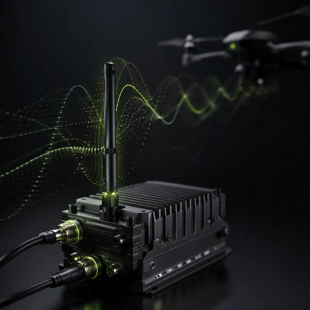
Every UAV programme has a radio link decision buried inside it, and that decision propagates through the entire system architecture. The band you choose sets hard limits on range, data throughput and latency. The protocol layer determines whether your telemetry stream arrives as clean packets or as a stuttering sequence of retransmissions. And the regulatory environment — CE in Europe, FCC in North America, SRRC in China — dictates which bands you can legally operate in your target market.
For procurement teams and system integrators, the communication layer is one of the easiest places to over-spec or under-spec. A 2.4 GHz link that works beautifully on a 500-metre inspection flight may drop packets at 5 km over open water. A 433 MHz link with 30 km range will struggle if your aircraft streams 1080p video. Matching the link to the mission is a structural decision — it shapes antenna placement, power budget, EMI management and payload compatibility — and it deserves the same engineering attention as motor sizing or flight controller and ESC matching.
The four frequency bands at a glance
Industrial UAVs operate across four primary frequency bands, each occupying a distinct position on the range-versus-throughput curve. The table below captures the headline numbers; the sections that follow unpack the real-world behaviour behind them.
| Band | Typical Range | Data Rate | Latency | Best For |
|---|---|---|---|---|
| 433 MHz | 15–50 km | Low (~10–50 kbps) | High (100–300 ms) | Long-range telemetry only |
| 868/915 MHz | 10–30 km | Moderate (~50–250 kbps) | Medium (50–150 ms) | Telemetry + low-res video |
| 2.4 GHz | 0.5–15 km | High (up to 20+ Mbps) | Low (10–40 ms) | HD video + low-latency control |
| 4G/LTE | Unlimited (cellular coverage) | Variable (5–50 Mbps) | Variable (30–100 ms) | BVLOS, multi-vehicle fleets |
These numbers are starting points, not guarantees. Real-world performance depends on antenna gain patterns, terrain, RF noise floor at the operating site, and the quality of the transceiver's error-correction implementation. A well-engineered 868 MHz link with a directional tracking antenna will outperform a poorly integrated 2.4 GHz system at any range beyond 2 km, regardless of what the datasheet says.
 Concept illustration
433 MHz — When range trumps everything
The 433 MHz ISM band occupies the lowest frequency slot in the UAV communications toolkit, and that low frequency is both its superpower and its limitation. Sub-gigahertz signals diffract around obstacles rather than being absorbed by them. At 433 MHz, a 1-watt transmitter with a quarter-wave dipole antenna can push telemetry packets through foliage, light urban clutter and moderate terrain that would completely block a 2.4 GHz signal. This is why long-endurance fixed-wing mapping platforms and environmental monitoring UAVs operating in remote terrain often carry a 433 MHz telemetry link as their primary command-and-control channel.
The trade-off is data rate. At 433 MHz, available bandwidth is narrow — typically 25 kHz to 200 kHz per channel — which caps throughput at roughly 10 to 50 kbps with modern LoRa or FSK modulation. That is sufficient for MAVLink telemetry packets, GNSS position updates, and low-frequency sensor data. It is not sufficient for video. A 433 MHz link transmitting at 50 kbps can carry approximately six MAVLink 2 messages per second plus GPS position — enough for waypoint navigation and system health monitoring, but not for real-time attitude streaming or camera gimbal control at high update rates.
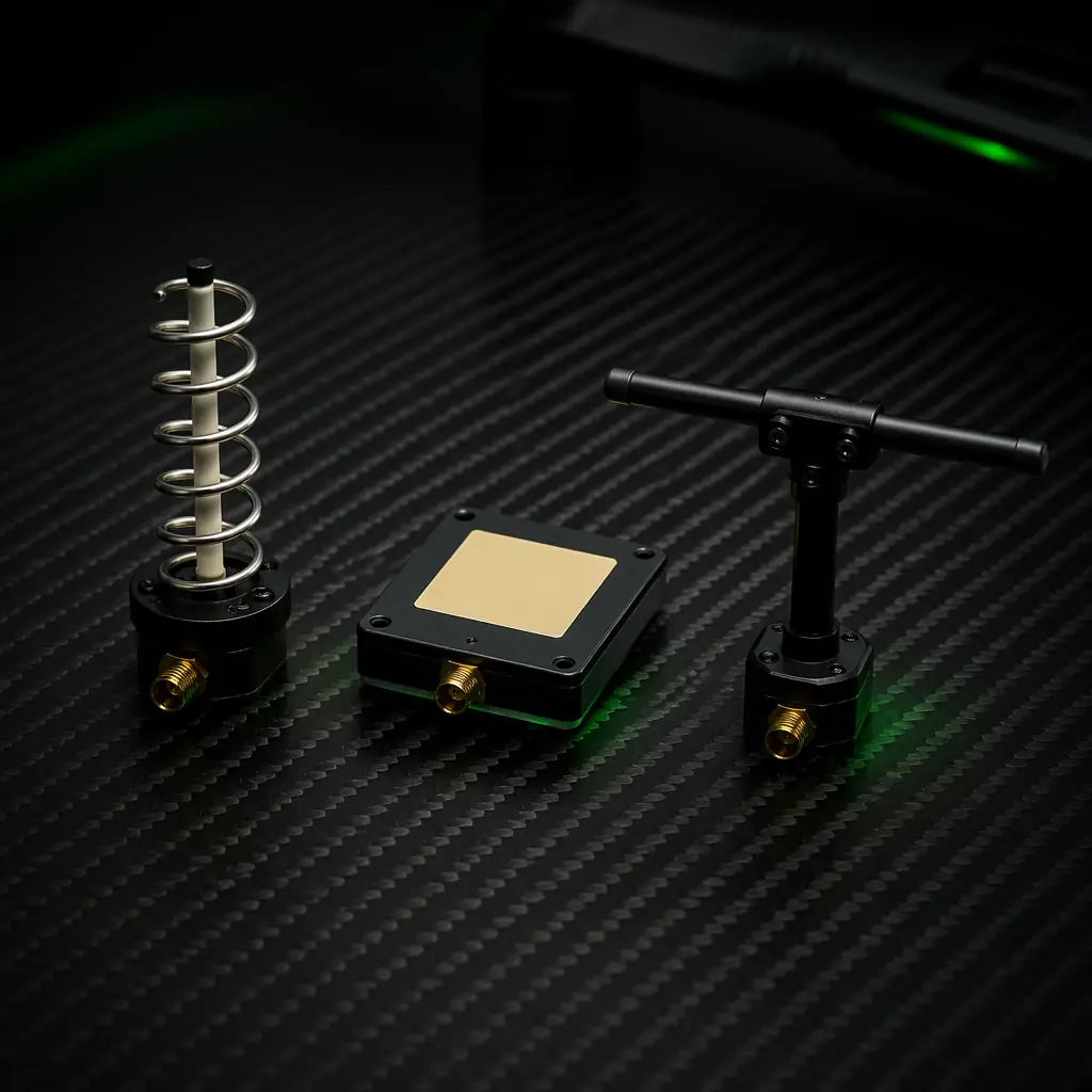
Antenna size is another practical constraint. A resonant quarter-wave antenna at 433 MHz is approximately 16.5 cm long. That is manageable on a 2-metre-wingspan fixed-wing but becomes an integration challenge on a compact quadcopter. Procurement teams specifying 433 MHz links for multirotor platforms should budget for antenna placement early — the ground plane geometry and distance from carbon fibre frame members directly affect radiation pattern and effective range. For platforms where airframe materials include carbon fibre (which is conductive and acts as an RF shield), antenna placement becomes one of the most constrained physical design decisions.
868/915 MHz — The regulatory sweet spot for industrial UAVs
The 868 MHz band (Europe, ETSI EN 300 220) and 915 MHz band (North America, FCC Part 15.247) represent the most widely adopted industrial UAV telemetry frequencies, and for good reason. They occupy the engineering sweet spot where range, throughput and antenna practicality intersect. At 868/915 MHz, a 500 mW transceiver with a modest 3 dBi omnidirectional antenna can sustain a 10 to 30 km link in clear air — the exact range band cited in the low-altitude economy component priorities article for civil UAV applications.
Data rates in this band typically range from 50 to 250 kbps depending on modulation scheme and channel bandwidth. LoRa modulation at spreading factor 7 can deliver roughly 5.5 kbps at the longest ranges, while GFSK or 4-FSK modulation on a 200 kHz channel can push 200 to 250 kbps at shorter range. Most industrial-grade 868/915 MHz radio modules — SiK, RFDesign, Holybro Telemetry — operate in the 50 to 200 kbps range, which is adequate for MAVLink telemetry, RTCM3 GNSS corrections for RTK positioning, and compressed low-frame-rate video (1–2 fps QCIF).
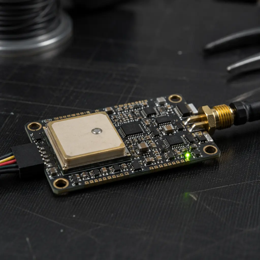
Regulatory compliance is the most important due-diligence item in this band. A module that is legal at 868 MHz under CE is not automatically legal at 915 MHz under FCC, even if the hardware supports both frequencies through firmware configuration. The duty cycle limits differ: ETSI limits 868 MHz sub-band G (869.4–869.65 MHz) to 10% duty cycle at 500 mW ERP, while FCC Part 15.247 allows higher duty cycles but imposes hopping or digital modulation requirements. Procurement teams shipping to multiple regions should verify that the radio module carries both CE and FCC grants, with the grant covering the specific modulation and output power the system will use in operation. The supplier evaluation checklist includes radio certification verification as a specific audit item — cross-check FCC IDs against the FCC OET database before accepting a supplier's compliance claim.
 Concept illustration
 Concept illustration
2.4 GHz — Bandwidth, ecosystem and the interference problem
The 2.4 GHz ISM band dominates consumer and prosumer UAV communication for one reason: bandwidth. With 83.5 MHz of available spectrum (versus roughly 2 MHz for 868 MHz in Europe), 2.4 GHz can sustain data rates of 20 Mbps and beyond using OFDM modulation — enough for 1080p30 video with room for telemetry, control and payload data on the same link. The ecosystem is vast: off-the-shelf chipsets from Qualcomm, Broadcom and MediaTek, mature Wi-Fi and proprietary protocol stacks, and a global allocation that makes 2.4 GHz legal in virtually every jurisdiction without band-specific certification aside from the standard FCC/CE radio emissions approval.
The limitation is range and interference resilience. At 2.4 GHz, free-space path loss is approximately 8.5 dB higher than at 868 MHz for the same distance — a factor of roughly 7× in linear power terms. A 100 mW 868 MHz transmitter reaches the same signal strength at 10 km that a 100 mW 2.4 GHz transmitter reaches at roughly 3.7 km, all else equal. In practice, the range gap is often wider because the 2.4 GHz band carries Wi-Fi access points, Bluetooth devices, microwave ovens, and other UAVs' video downlinks — all of which raise the noise floor and reduce effective sensitivity.
For industrial UAVs operating in urban or semi-urban environments, 2.4 GHz interference is not an edge case — it is the normal operating condition. A survey flight over an industrial park may encounter 50 to 200 Wi-Fi access points within receive range. FHSS (frequency-hopping spread spectrum) and DSSS (direct-sequence) modulation schemes provide some resilience, but they cannot create spectrum that is not there. The practical ceiling for 2.4 GHz range in a congested RF environment is often 500 metres to 2 km for a reliable link, well short of the 10+ km achievable in a rural environment. For teams building platforms that must operate in both environments, a dual-band architecture — 2.4 GHz for high-bandwidth short-range, 868/915 MHz for long-range telemetry — is the standard pattern, and it ties directly to the powertrain matching conversation in UAV powertrain matching, where onboard power budget must accommodate two independent RF chains.
4G/LTE — Beyond visual line of sight, with caveats
Cellular connectivity rewrites the range equation entirely. A UAV equipped with a 4G/LTE modem and a properly provisioned SIM card can maintain a command-and-control link anywhere within cellular coverage — which, in most of Europe, North America and developed Asia, means effectively everywhere below 120 metres AGL. This is the architectural foundation of beyond-visual-line-of-sight (BVLOS) operations, multi-vehicle fleet management, and cloud-connected UAV services.
The bandwidth is shared and variable. In good signal conditions on an uncongested LTE cell, a UAV modem can sustain 5 to 20 Mbps downlink and 2 to 10 Mbps uplink, with latency in the 30 to 80 ms range. In poor conditions — cell edge, network congestion, handover between towers — latency can spike to 200 to 500 ms and throughput can drop below 1 Mbps. For a UAV flying at 15 m/s, a 500 ms latency spike represents 7.5 metres of travel between sending a command and receiving confirmation. That is acceptable for waypoint navigation but unacceptable for precision landing or obstacle avoidance at low altitude.
Network handover is the hardest engineering problem in cellular UAV links. A ground-based phone transitions between towers while moving at pedestrian or vehicle speeds on a roughly two-dimensional plane. A UAV transitions between towers while moving in three dimensions at potentially higher speeds, and the antenna radiation pattern of a cell tower is optimised for ground-level coverage — not for a transmitter 100 metres above the tower. At altitude, a UAV may see multiple towers with similar signal strength, causing rapid ping-pong handovers that degrade link quality. Industrial-grade cellular UAV modems address this with multi-SIM aggregation, antenna diversity (typically 2×2 or 4×4 MIMO), and firmware-level handover optimisation — but these features add cost and integration complexity.
For procurement teams, the cellular question is operational rather than purely technical. A platform that flies exclusively within cellular coverage and tolerates occasional latency spikes can operate on a single 4G link. A platform that must fly beyond cellular coverage or cannot tolerate latency variability needs a hybrid architecture — 4G for cloud connectivity and high-bandwidth payload data, paired with a licensed or ISM-band telemetry link for safety-critical command and control.
Redundancy architectures: two links are safer than one
Single-link UAV communication architectures create a single point of failure between the aircraft and the ground. For any platform carrying a payload worth more than the radio hardware, a redundant link architecture is usually the right engineering investment. The three most common patterns are:
- Dual-band telemetry — one 868/915 MHz link and one 433 MHz link carrying the same MAVLink stream. The 868/915 MHz link provides primary telemetry at higher data rates; the 433 MHz link provides a fallback with deeper signal penetration. If the primary link drops, the flight controller automatically routes telemetry through the secondary link. This is the standard architecture for long-range mapping and survey platforms.
- Telemetry + cellular — an ISM-band telemetry link for low-latency C2 (command and control), paired with a 4G/LTE link for payload data, cloud telemetry logging and fleet management. The ISM link is safety-critical; the cellular link is mission-critical but not flight-critical. If cellular drops, the aircraft continues flying on ISM-band C2 and buffers payload data for later upload.
- Dual cellular with satellite fallback — two independent cellular modems on different carrier networks, with an Iridium or Inmarsat satellite terminal for C2 in areas without any cellular coverage. This architecture is expensive but is required for truly global BVLOS operations such as maritime surveillance or cross-continent pipeline inspection.
Redundancy adds weight, power draw, antenna count and integration complexity — all of which feed back into the build versus buy sourcing decision. A matched propulsion-and-communications subsystem from a single vendor may integrate antenna placement, power distribution and EMI shielding better than a team assembling radios, cables and antennas from four different suppliers.
 Concept illustration
How to choose: a decision framework
Radio link selection does not start with a frequency — it starts with the mission profile. Until you know the range, the payload data type, and the operating environment, frequency band comparisons are abstract. The following framework walks through the five questions that narrow the decision to one or two bands, at which point vendor selection and certification verification become the next steps.
Question 1: What is your maximum operational range, including safety margin? Take the longest distance the aircraft will fly from the ground station and add 30%. If that number is below 2 km and the operating environment is not RF-congested, 2.4 GHz is viable. Between 2 and 15 km, 868/915 MHz becomes the primary candidate. Above 15 km, 433 MHz or cellular — and above 30 km, cellular or satellite — become the only practical options.
Question 2: What data must the link carry? Telemetry only (MAVLink at 10–50 kbps): any band works. Telemetry plus compressed video at 1–2 fps: 868/915 MHz or above. HD video at 1080p: 2.4 GHz or 4G/LTE. Multi-sensor payload data at 10+ Mbps: 4G/LTE or a dedicated 2.4 GHz OFDM link. Be honest about the data budget — a link that is saturated at cruise throttle leaves no headroom for emergency retransmissions or firmware updates over the air.
Question 3: What is the RF environment at the operating site? Urban: expect heavy 2.4 GHz congestion, moderate 868/915 MHz, and reliable 4G. Rural: 2.4 GHz opens up to longer ranges, 868/915 MHz performs close to theoretical maximums, and 4G may be patchy. Industrial: expect electromagnetic interference from machinery, power lines and metal structures across all bands — favour lower frequencies for penetration and budget for antenna diversity. Maritime or over-water: signal reflection off the water surface creates multipath fading that affects all bands; antenna height and circular polarisation matter more than frequency choice.
Question 4: Which regulatory domains must the platform operate in? Map your target markets to frequency allocations. CE (Europe): 868 MHz SRD band, 2.4 GHz, 4G. FCC (North America): 915 MHz ISM, 2.4 GHz, 4G. Other jurisdictions: check local allocations — 433 MHz is not universally available for airborne use, and some countries restrict 900 MHz to fixed services only. If the platform ships to multiple regions, either specify a multi-band radio with region-locked firmware or accept the cost and weight of carrying two radio modules with different bands. The UAV supply chain layers article covers the procurement implication: a radio module that needs separate SKUs for CE and FCC markets doubles the qualification and inventory burden.
Question 5: Does the mission require redundancy? If a lost link means a lost aircraft or a safety incident, the answer is yes. Budget for two independent RF paths — different bands, different antennas, different power supplies if possible. The cost of a second radio module and antenna is almost always less than the cost of a single lost-aircraft incident, even before accounting for downtime and reputation.