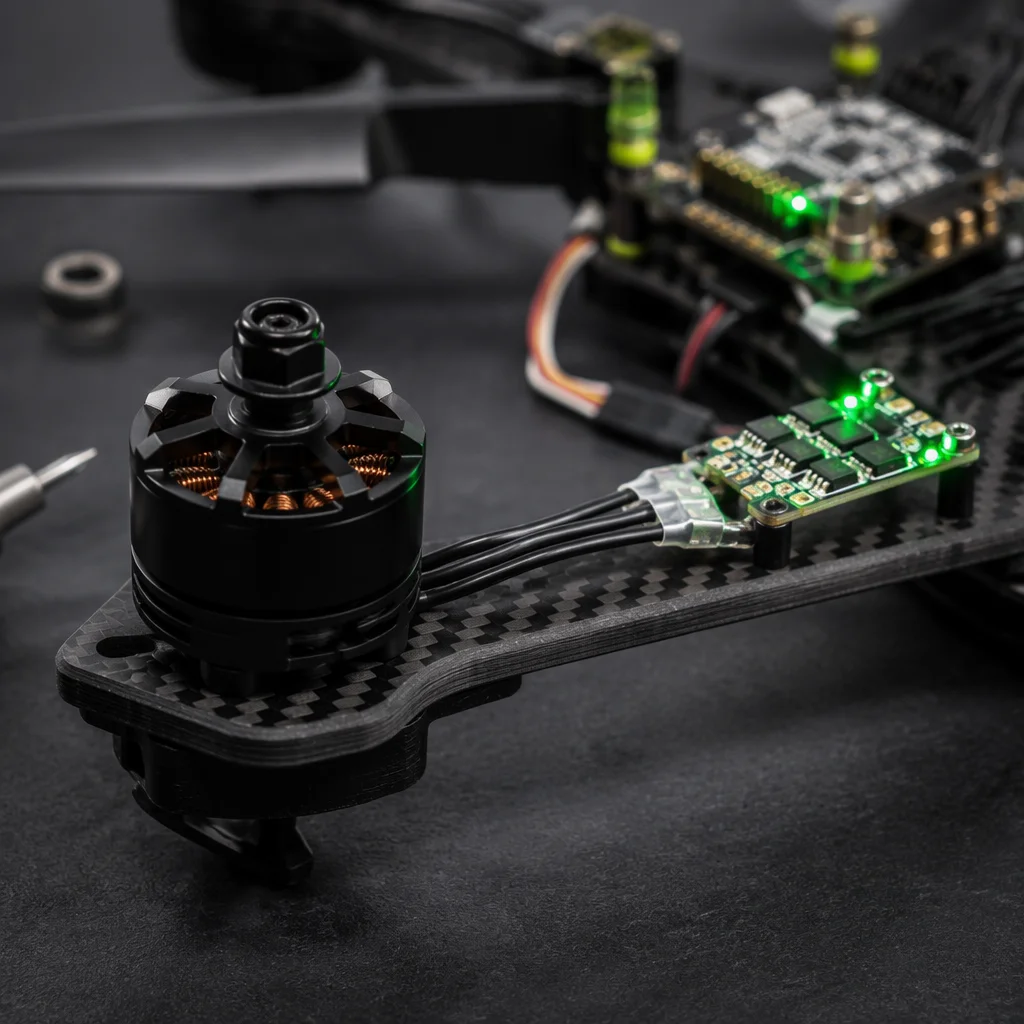
Many engineering teams treat the flight controller, ESC and motor as independent procurement items. On paper each part has its own datasheet, its own evaluation criteria and its own supplier. In the aircraft those three components share voltage rails, control protocols and a common current path. A mismatch at any interface creates risk that no single datasheet can warn you about.
Why the powertrain chain matters
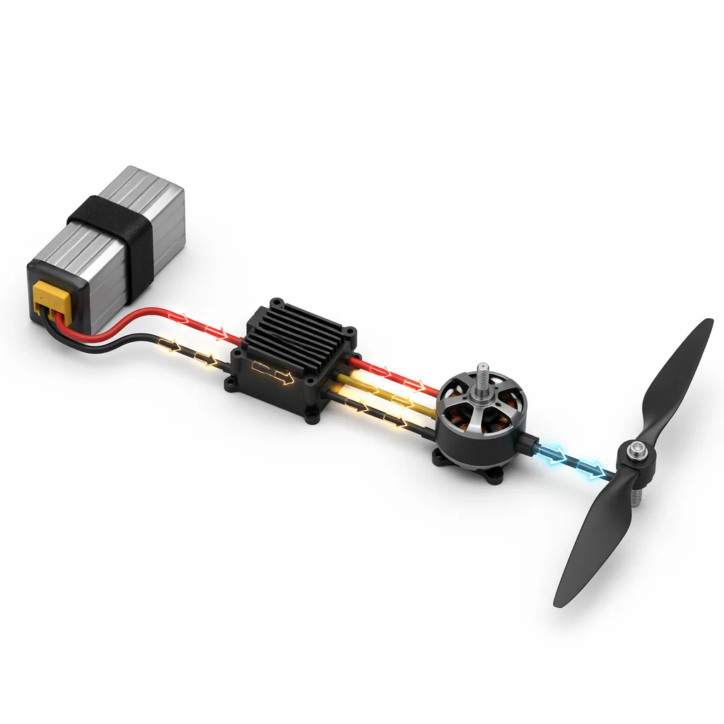
The powertrain is not three separate choices — it is one closed electrical and logical loop. The battery voltage feeds the ESC, the ESC modulates current to the motor under commands from the flight controller, and the motor spins the propeller against aerodynamic resistance. Every decision in that chain constrains the next.
Voltage architecture determines the ESC input range and the motor KV ceiling. The ESC protocol determines which flight controllers can speak to it and with what telemetry bandwidth. The motor KV and propeller size together set the current draw — and if the ESC current rating was chosen in isolation, that draw can push it past its thermal margin. These are not edge cases. They are the normal consequence of catalog-first sourcing.
Step 1: Start with voltage
The battery voltage — 3S through 12S for LiPo packs, or 6S through 14S for Li-Ion — sets the floor for every downstream choice. Higher voltage reduces current for the same power output, allowing thinner wiring harnesses and cooler-running ESCs. But it also demands lower KV motors and a flight controller whose power input stage can handle the rail without overheating.
A practical reference: 4S systems suit small inspection quads under 2 kg all-up weight. 6S covers the mid-size industrial range — mapping drones, agricultural sprayers and light cargo platforms in the 3 to 10 kg class. 12S and above is the territory of heavy-lift multirotors carrying LiDAR rigs, cinematography gimbals or delivery payloads above 15 kg. Selecting voltage first prevents the common mistake of locking a motor and ESC pair then discovering the battery weight makes the airframe unworkable.
Step 2: ESC protocol and current headroom
Modern ESCs communicate over several protocol families: BLHeli_32 and AM32 offer fast digital protocols with RPM and temperature telemetry; CAN-bus ESCs provide robust industrial control with error-checked frames; traditional PWM remains available for legacy compatibility. The flight controller must speak the same protocol — an FC with only PWM outputs cannot drive a CAN ESC without an adapter, and that adapter introduces latency the control loop may not tolerate.
Current rating needs 20–30% headroom above the maximum expected draw. A motor that pulls 40 A at full throttle under static load will spike higher in gust recovery or during a rapid climb. An ESC rated for exactly 40 A continuous leaves no margin for transients. Also consider the form factor: 4-in-1 ESC boards save weight and wiring but concentrate heat and create a single point of failure. Individual ESCs on the arms offer better cooling and field-replaceability, at the cost of a more complex harness. The trade-off depends on the mission — a survey drone that must stay airborne for 45 minutes values the weight saving; a heavy-lift platform flying over infrastructure values the serviceability.
Step 3: Motor KV and propeller load
KV rating multiplied by voltage gives the unloaded RPM — but the propeller diameter, pitch and blade count determine the actual mechanical load the motor sees. A high-KV motor on a large propeller behaves like a stalled transmission: the motor demands current the winding was not sized for, and thermal runaway follows within seconds at full throttle.
The matching logic is straightforward once you frame it as a table:
| Motor Size (stator) | Typical KV Range | Propeller Range | Typical Thrust (per motor) |
|---|---|---|---|
| 22xx–23xx | 1800–2450 KV | 5–6 inch | 0.8–1.5 kg |
| 28xx–31xx | 700–1200 KV | 9–13 inch | 2.0–4.5 kg |
| 35xx–40xx | 340–580 KV | 15–18 inch | 4.0–8.0 kg |
| 50xx–62xx | 120–340 KV | 20–30 inch | 8.0–18.0 kg |
These ranges represent common industrial configurations at 6S to 12S. Always verify against the specific motor manufacturer's thrust table for your propeller and voltage combination. A bench test with a watt meter is the only way to confirm the real current draw before committing to production quantities.
 Concept illustration
Step 4: Interface checklist before ordering
Before placing orders, verify every interface in the chain. A one-hour checklist review costs far less than a failed integration:
- Voltage range compatibility — Confirm the FC power input, ESC voltage rating and motor winding all share a common operating voltage band with headroom for sag and ripple.
- Connector types and pinouts — ESC signal connectors, motor bullet size, battery connector type and current rating. Mismatched connectors add resistance, weight from adapters and assembly errors.
- Firmware support — Verify that ArduPilot, PX4 or Betaflight has a parameter file or configuration target for your FC–ESC combination. A controller with no firmware target means weeks of porting work.
- BEC and power distribution — Map the power tree: battery to PDB to ESCs, plus regulated outputs for the FC, radio receiver, payload interface and any servo-driven mechanisms. A missing BEC rail is a common reason builds stall on the bench.
- Telemetry feedback path — RPM, current draw and ESC temperature are not optional for industrial aircraft. Confirm the ESC protocol carries telemetry and that the FC firmware logs it. A hot ESC in flight is a warning you need to receive.
Education, not a case study
This article is an engineering primer on powertrain component matching. It does not describe a specific customer deployment, capacity claim or certified production outcome. Exact ratings, protocols and compatibility should be validated against your project brief and the manufacturer's current datasheets.