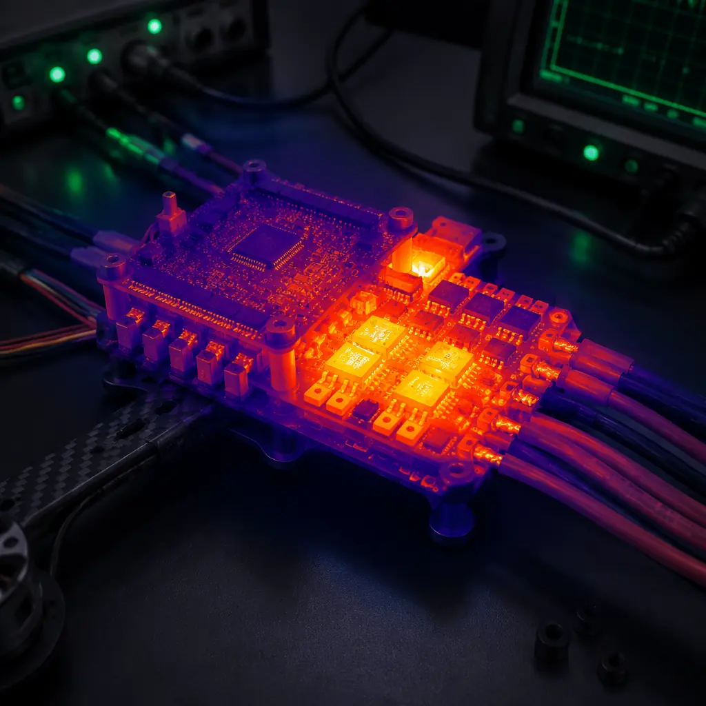
In the UAV electronics supply chain, thermal specifications are the most frequently under-specified parameter on a component datasheet. A flight controller that lists an operating temperature range of -20°C to +85°C tells the procurement team only that the PCB assembly passed a bench-top temperature chamber soak — it does not tell them what happens to the IMU bias stability at 75°C, what the barometer's pressure reading offset is at 60°C after 30 minutes of self-heating, or whether the 3.3 V LDO regulator enters thermal shutdown when the board is mounted inside a sealed avionics bay with zero forced airflow on a 40°C summer day at low altitude. Thermal management in UAV electronics is a system-level problem that spans the component selection (choosing parts with acceptable thermal drift specifications), the PCB layout (thermal via density under high-power components, copper pour area for heat spreading), the mechanical integration (airflow paths through the airframe, thermal interface materials between the ESC power stage and the arm heatsink, battery compartment ventilation), and the operational envelope (ambient temperature range, maximum sustained current duration, duty cycle between high-power and low-power flight phases).
This article approaches thermal management from the procurement and integration perspective: what thermal specifications to request from component suppliers, how to verify that a flight controller or ESC can sustain its rated performance across the full mission temperature envelope, and what passive and active cooling strategies are available at each level of the UAV electronics stack. The thermal behavior of the propulsion system — motor winding temperature rise under sustained load — is covered in the UAV powertrain matching guide, which provides the motor current-to-temperature mapping that is the input to the ESC thermal analysis. This article focuses on the electronics: the PCBs, power semiconductors, sensors and battery cells whose thermal limits are narrower than the motor's and whose failure modes — unlike a motor that simply loses efficiency as it heats up — include complete loss of flight control authority.
Heat sources in a UAV electronics stack: where the watts go
A UAV electronics stack dissipates heat from four primary sources, each with a different thermal time constant and a different sensitivity to ambient temperature. Understanding the magnitude and location of each heat source is the prerequisite to designing a thermal management strategy that addresses the right component with the right cooling mechanism.
ESC power stage MOSFETs. The largest single heat source in the electronics stack. A typical 6S ESC delivering 40 A continuous to a motor will dissipate 6–12 W of heat in the MOSFET bridge, depending on the MOSFET RDS(on) at the operating temperature — and RDS(on) increases with temperature, creating a positive feedback loop where rising temperature increases resistance, which increases dissipation, which further increases temperature. A MOSFET with RDS(on) of 2.5 mΩ at 25°C will have RDS(on) of approximately 3.8 mΩ at 100°C junction temperature — a 52% increase. The thermal time constant of the MOSFET junction-to-case path is on the order of 100–500 milliseconds, meaning the MOSFET temperature tracks the motor current almost instantaneously. A current spike during a rapid climb — 50 A for 3 seconds — will push the MOSFET junction temperature 15–25°C above its steady-state value within the first second of the spike, well before the heatsink has time to respond. Thermal management for ESCs must therefore address both the steady-state dissipation (with a heatsink sized for the average current over a complete flight) and the transient thermal impedance (with sufficient copper area on the PCB directly under the MOSFET package to absorb the thermal spike without exceeding the maximum junction temperature, typically 150–175°C for silicon MOSFETs used in UAV ESCs).
 Concept illustration
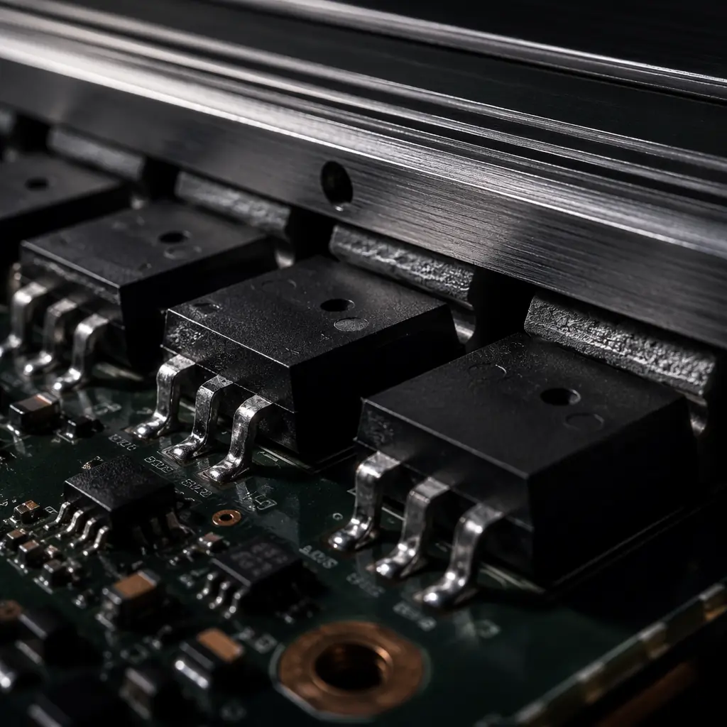
Flight controller voltage regulators. The flight controller typically accepts battery voltage (12–50 V) and regulates it down to 5 V (for servo outputs, GNSS receiver, telemetry radio) and 3.3 V (for the microcontroller, IMU, barometer, magnetometer and SD card). The voltage drop across the LDO or switching regulator is dissipated as heat. A linear regulator dropping 22.2 V (6S nominal) to 5 V at 500 mA load dissipates (22.2 - 5) × 0.5 = 8.6 W — more heat than the ESC MOSFETs in some configurations, concentrated in a single SOT-223 or TO-252 package with a junction-to-ambient thermal resistance of 40–60°C/W in still air. At 8.6 W dissipation, the junction temperature rise above ambient is 8.6 × 50 = 430°C — far exceeding the regulator's thermal shutdown threshold (typically 150°C), which means the regulator will enter thermal shutdown within seconds of power-up. This is why industrial UAV flight controllers use switching regulators (buck converters) for the 5 V rail: a buck converter with 90% efficiency dissipates only 0.5 W for the same 5 V, 500 mA output, producing a junction temperature rise of only 25°C — well within the safe operating area. The procurement specification for a flight controller must therefore distinguish between "rated for 6S input" (which a linear regulator can claim on a datasheet if it survives the absolute maximum voltage rating) and "rated for 6S continuous operation at 55°C ambient with all sensors and interfaces active" (which requires a switching regulator with adequate thermal design).
Battery cells under discharge. A LiPo or Li-Ion battery pack dissipates heat through its internal resistance — typically 2–8 mΩ per cell for high-discharge LiPo packs used in UAVs. At 40 A continuous discharge from a 6S pack, the total internal dissipation is I²R = 40² × (6 × 0.005) = 48 W for a pack with 5 mΩ per cell. This heat is distributed across the entire pack volume and must be conducted through the cell packaging, the inter-cell spacers and the pack enclosure to the ambient air. The thermal time constant of a battery pack is much longer than the electronics — 10–30 minutes for a typical 6S 10,000–22,000 mAh UAV pack — which means the pack temperature rises steadily throughout the flight and peaks 5–10 minutes after landing, when the heat generated during the final high-power landing phase has conducted to the pack surface but the airflow from forward flight has stopped. Battery thermal management is covered in detail in the UAV battery and power management guide; this article addresses the interaction between battery heating and the thermal environment of the adjacent electronics — a battery pack at 55°C mounted 20 mm from a flight controller enclosure will raise the flight controller's ambient temperature by 10–15°C through radiative and convective coupling, effectively reducing the flight controller's thermal margin by the same amount.
RF power amplifier in communications modules. A UAV telemetry radio or video transmitter operating at 1 W (+30 dBm) RF output power with a typical power amplifier efficiency of 40–50% dissipates 1.0–1.5 W of heat in the PA stage. While this is a smaller heat source than the ESC or voltage regulator, the PA is typically in a small QFN or LGA package with limited thermal mass, and it is often mounted on a communications module PCB that has minimal copper area for heat spreading — the module was designed as a standalone product, not as a component in a thermally constrained UAV avionics bay. The result is a PA junction temperature that can exceed 100°C in still air at 40°C ambient, reducing the PA's gain, output power and linearity. For UAVs with sealed avionics bays — common in agricultural spraying UAVs where the electronics must be protected from chemical drift — the communications module should be specified with a conductive thermal path to the enclosure wall (a thermal pad or gap filler between the PA package and the aluminum enclosure) or the module's transmit duty cycle should be limited in firmware to prevent sustained high-temperature operation.
Passive cooling: the first line of thermal defense
Passive cooling — heat dissipation without moving parts — is the default thermal management strategy for UAV electronics because it adds zero weight, zero power consumption and zero failure modes. The three passive cooling mechanisms are conduction (heat flow through a solid material from a hot component to a cooler surface), convection (heat transfer from a surface to the surrounding air, driven by the UAV's forward airspeed and propeller downwash), and radiation (heat transfer via electromagnetic radiation between surfaces at different temperatures). At the temperatures encountered in UAV electronics — typically 40–90°C at the component surface — radiation accounts for less than 15% of the total heat transfer; conduction and convection dominate.
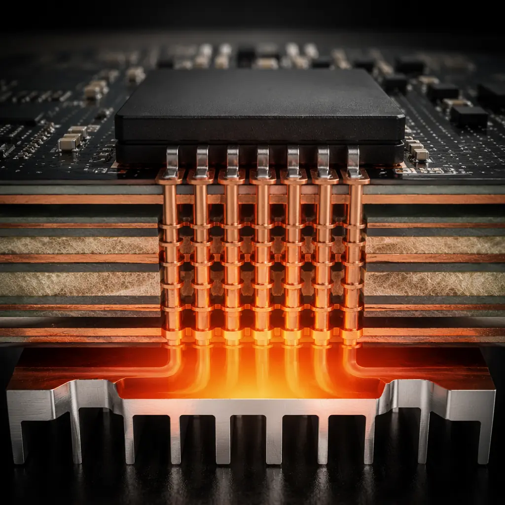
Conduction: the PCB as a heatsink. The most cost-effective and weight-efficient passive cooling mechanism for UAV electronics is the PCB itself. A standard 4-layer PCB with 1 oz/ft² (35 μm) copper on each layer has a total copper thickness of 140 μm — equivalent to approximately 70 μm of a typical aluminum heatsink, but with the advantage that the copper is bonded directly to the component's thermal pad through solder, eliminating the thermal interface material resistance that accounts for 30–50% of the total junction-to-ambient thermal resistance in a discrete heatsink assembly. The thermal via — a plated through-hole connecting the component's thermal pad on the top layer to a copper pour on an inner or bottom layer — is the primary heat conduction path from a surface-mount component to the PCB's internal copper planes. A thermal pad with a 4 × 4 array of 0.3 mm diameter thermal vias, each with 25 μm of plated copper on the via wall, provides a total via cross-sectional area of approximately 0.28 mm² of copper — equivalent to a solid copper cylinder 0.6 mm in diameter, with a thermal resistance of approximately 15–25°C/W from the component pad to the inner copper plane. A procurement specification for a flight controller or ESC intended for high-temperature operation should require a thermal via density of at least 16 vias under each power component (MOSFET drain tab, LDO thermal pad, buck converter switch node) and a minimum of 2 oz/ft² (70 μm) copper on the power-carrying layers.
 Concept illustration
Convection: using the UAV's own airflow. The propeller downwash and forward-flight airstream provide forced convection cooling with zero additional system weight — but only if the electronics are placed in the airflow path. A flight controller mounted inside a sealed avionics bay with no ventilation openings receives essentially zero convective cooling, and its only heat rejection path is conduction to the airframe structure (if a thermal interface material is present between the PCB mounting points and the airframe) and radiation to the bay walls. The difference in effective heat dissipation between an ESC mounted in the propeller downwash (air velocity 8–15 m/s at hover for a 15-inch propeller, producing a convective heat transfer coefficient of 40–80 W/m²·K on the ESC surface) and the same ESC mounted in a sealed bay (natural convection only, heat transfer coefficient 5–10 W/m²·K) is a factor of 5–10 — meaning the ESC in the sealed bay must dissipate the same heat through a much smaller thermal gradient, resulting in a junction temperature 40–60°C higher for the same electrical load.
The practical procurement implication is that the ESC's continuous current rating is not a single number — it is a function of the mounting condition. An ESC rated for 40 A continuous with "adequate airflow" (typically defined by the manufacturer as 5 m/s air velocity across the heatsink) may be rated for only 25 A continuous in still air, and for 15 A continuous in a sealed enclosure at 55°C ambient. The procurement specification must state the airflow condition under which the current rating applies, and the UAV integrator must verify that the actual mounting condition in the airframe meets or exceeds this airflow condition. If the airframe design places the ESC in a location with restricted airflow — inside a carbon fiber tube arm, behind a payload mounting bracket that blocks the propeller downwash, or inside a sealed electronics pod — the ESC must be de-rated accordingly or an alternative cooling strategy (active cooling or conductive cooling to the airframe) must be implemented. The flight controller and ESC matching guide covers the electrical compatibility constraints; this thermal de-rating is an additional constraint that must be applied on top of the electrical matching.
Radiation and enclosure design. Aluminum enclosures with anodized surfaces have an emissivity of 0.75–0.85, meaning they radiate 75–85% of the heat that a perfect blackbody radiator would emit at the same temperature. An ESC heatsink with a surface area of 50 cm² at 70°C in a 40°C ambient environment radiates approximately 1.5–2.0 W of heat — a small but non-zero contribution that can make the difference between the ESC operating at 95°C (below the typical 105°C thermal throttling threshold) and 105°C (at which the ESC begins reducing output current to protect itself). The enclosure surface finish matters for radiation: a black anodized surface has approximately 30% higher emissivity than a bare aluminum surface, and a painted surface (with a paint that is opaque in the infrared) can achieve emissivity of 0.90–0.95. For UAV electronics enclosures that are visible on the exterior of the airframe — ESC heatsinks on the arms, telemetry radio enclosures on the tail boom — the procurement specification should include a surface finish requirement that balances the thermal emissivity benefit against the aesthetic and corrosion-resistance requirements.
Active cooling: when the thermal budget exceeds passive capacity
Active cooling — forced airflow from a dedicated fan or blower — adds weight (typically 15–50 grams for a 30–40 mm fan), power consumption (0.5–3 W), and a single-point failure mode (fan stall due to dust ingestion, bearing wear or impact damage) to the UAV electronics thermal management system. It should be specified only when passive cooling cannot maintain component temperatures within their rated limits across the full mission envelope, and it should be designed with a fail-safe strategy: if the fan fails, the UAV must either complete the mission at reduced power (if the flight controller can detect the fan failure through a tachometer signal and command the ESCs to a reduced current limit) or abort the mission and return to launch before component temperatures reach their thermal shutdown threshold.
Fan selection for UAV avionics bays. A 40 mm axial fan operating at 5 V and 0.15 A (0.75 W) produces approximately 8–12 CFM (cubic feet per minute) of airflow — sufficient to reduce the junction-to-ambient thermal resistance of a typical ESC assembly from 12°C/W (natural convection) to 4–6°C/W (forced convection at 8 CFM across the heatsink). This reduces the ESC MOSFET junction temperature by 30–50°C for the same electrical load, effectively doubling the ESC's continuous current rating in the same thermal environment. The fan specification for UAV use should include: operating voltage compatible with the UAV's regulated power rail (5 V or 12 V), tachometer output (a third wire that provides a pulse per revolution, allowing the flight controller to monitor fan speed and detect stall), ingress protection rating (IP54 minimum for outdoor UAV use, protecting against dust ingress and water spray — agricultural spraying UAVs should specify IP65 or higher due to chemical exposure), and mean time between failures (MTBF) at the expected operating temperature (a fan rated for 50,000 hours MTBF at 25°C may have an MTBF of only 10,000–15,000 hours at 60°C, which is the actual air temperature inside the avionics bay after 20 minutes of flight).
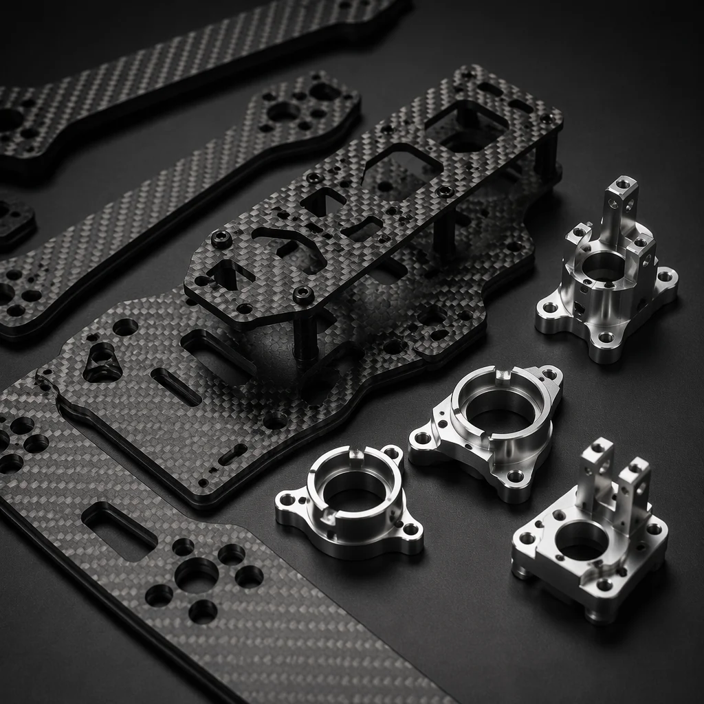
Conduction to airframe as active cooling. An alternative to a dedicated fan is conductive coupling of the ESC heatsink to a carbon fiber or aluminum airframe component that acts as an extended heat spreader — effectively using the airframe's surface area as a passive radiator exposed to the propeller downwash and forward-flight airstream. This approach requires a thermal interface material between the ESC heatsink and the airframe mounting surface, and the airframe component must have sufficient thermal conductivity — carbon fiber's in-plane thermal conductivity is 5–15 W/m·K (adequate for heat spreading over distances of 50–100 mm), while its through-thickness conductivity is only 0.5–1.0 W/m·K (poor, requiring a metal insert or thermal via equivalent at the mounting point). Aluminum airframe components have thermal conductivity of 150–200 W/m·K — approximately 10–40 times higher than carbon fiber — and can spread heat over distances of 200–500 mm with minimal temperature drop, making them effective heat sinks for ESC and flight controller thermal management. The UAV airframe materials guide covers the thermal conductivity of each airframe material in more detail, including the anisotropic thermal behavior of carbon fiber laminates that determines the effective heat-spreading distance.
Thermal interface materials: the 0.1 mm layer that determines junction temperature
The thermal interface material (TIM) between a component's thermal pad and the heatsink or PCB copper pour is the highest-resistance element in the conduction path from junction to ambient. A typical TIM — a silicone-based thermal pad with a thickness of 0.5–1.0 mm and a thermal conductivity of 1–3 W/m·K — contributes a thermal resistance of 2–5°C/W for a MOSFET with a 5 × 6 mm thermal pad area. This is 30–50% of the total junction-to-ambient thermal resistance for a well-designed ESC with an aluminum heatsink, meaning the TIM specification is as important as the heatsink size in determining the component's operating temperature.
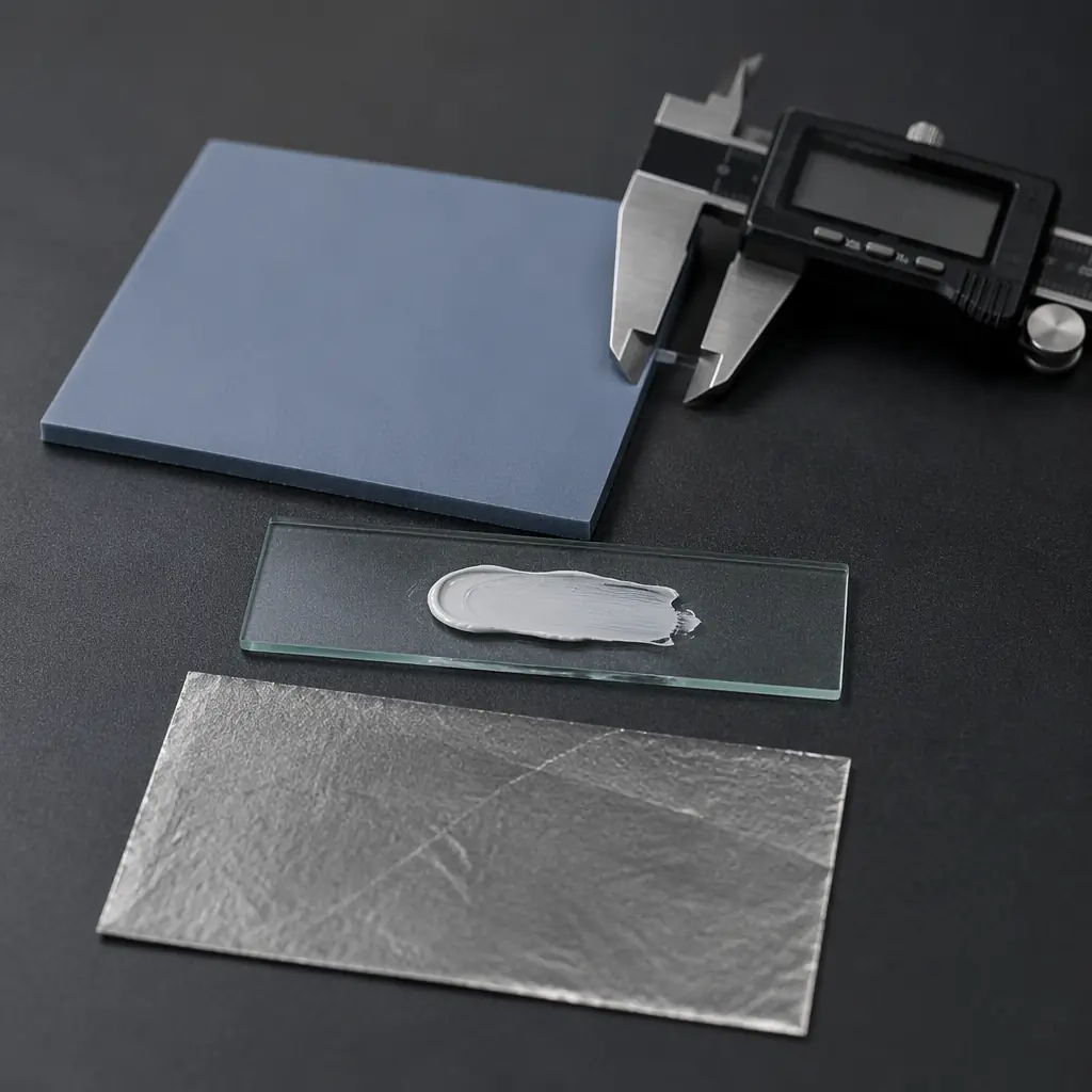
TIM types and procurement specifications. Three TIM types are used in UAV electronics, each with a distinct performance envelope and procurement requirement. Thermal pads (pre-cured silicone or acrylic sheets filled with ceramic particles — aluminum oxide, boron nitride, or zinc oxide — with thermal conductivity of 1–8 W/m·K) are the most common because they are easy to apply (peel-and-stick), require no curing, and can accommodate surface roughness and flatness variation between the component and the heatsink. The procurement specification for a thermal pad should include: thermal conductivity (measured per ASTM D5470, not the manufacturer's marketing number — many "6 W/m·K" pads measure 2–3 W/m·K in independent testing), thickness (0.5 mm is the practical minimum for UAV electronics to accommodate PCB warpage and component height variation; thinner pads have lower thermal resistance but risk incomplete contact if the mounting surfaces are not flat within 0.05 mm), hardness (Shore 00 scale, 30–60 is typical — softer pads conform better to surface irregularities but are more susceptible to compression set over time), and operating temperature range (-40°C to +150°C for silicone-based pads, sufficient for all UAV electronics applications).
Thermal grease (silicone or non-silicone paste with ceramic or metal particle fillers, thermal conductivity 3–10 W/m·K) provides lower thermal resistance than pads — typically 0.5–1.5°C/W for the same MOSFET package — because it fills surface irregularities at the micrometer scale without the bulk thermal resistance of a pad. The trade-off is application complexity: thermal grease requires a controlled dispensing process and a clamping mechanism that maintains consistent pressure across the component surface, and it is susceptible to pump-out (the grease migrates out of the interface gap due to thermal cycling, leaving voids that increase thermal resistance over time). Thermal grease is appropriate for high-power UAV ESCs (continuous current above 60 A per motor) where the thermal resistance reduction justifies the assembly process complexity, and for applications where the ESC is a non-field-replaceable unit that is assembled once and not disassembled for maintenance. Phase-change materials (thermoplastic compounds that melt at the component's operating temperature — typically 45–65°C — and flow to fill surface irregularities, then re-solidify when the component cools) combine the application convenience of a pad with the thermal performance approaching that of grease, but they are more expensive (USD 0.50–2.00 per MOSFET vs USD 0.10–0.30 for a pad) and require a burn-in cycle after assembly to initiate the phase change and achieve the design thermal resistance.
 Concept illustration
Thermal management specifications for component procurement
When procuring flight controllers, ESCs and communications modules for a UAV platform, the following five thermal specifications should be requested from every supplier. A supplier that cannot provide three of these five specifications is not treating thermal management as a design parameter — and their component will become the thermal bottleneck in the UAV stack.
1. Maximum junction temperature at rated continuous current, with airflow specification. The supplier must state the MOSFET junction temperature (for ESCs) or the regulator junction temperature (for flight controllers) at the rated continuous current, with the airflow condition clearly specified — for example, "Tj = 105°C at 40 A continuous, 5 m/s airflow, 25°C ambient." Without the airflow condition, the temperature number is meaningless. A supplier that states "operating temperature: -20 to +85°C" without specifying the electrical load and airflow condition under which that range applies is providing an environmental rating, not a thermal specification.
2. Thermal derating curve: current vs ambient temperature. The supplier must provide a graph or table showing the maximum continuous current as a function of ambient temperature, from -20°C to +70°C, at the specified airflow condition. This curve tells the procurement team what current the ESC can sustain when the UAV operates in a 45°C desert environment versus a 15°C maritime environment — and it reveals whether the component has adequate thermal margin for the intended operational envelope. A component whose rated current drops by 40% between 25°C and 55°C ambient requires either active cooling or a larger (heavier, more expensive) component with more thermal margin. The thermal derating curve is the single most useful thermal document for UAV integration, and it is the document most frequently absent from component datasheets. The supplier evaluation checklist includes thermal documentation as evaluation criterion number 7 — a supplier that cannot produce a thermal derating curve during the qualification audit is flagged as high risk for thermal integration issues.
3. Thermal protection behavior: throttling threshold and recovery hysteresis. The supplier must describe exactly what happens when the component reaches its thermal limit. Does the ESC reduce output current linearly above a temperature threshold (proportional throttling), or does it cut output completely (thermal shutdown)? What is the throttling threshold temperature, and what is the hysteresis — the temperature drop required before full current output is restored? A thermal shutdown with 20°C hysteresis — the component cuts output at 110°C and does not restore it until the temperature drops to 90°C — means the UAV loses power for several minutes after a thermal event, which may exceed the time available for a controlled landing on battery reserve. A proportional throttle-back at 105°C to 50% current, with recovery to 100% at 100°C, is a much more survivable thermal protection strategy for a UAV that can complete its mission (or at least return to launch) on reduced power.
4. Sensor thermal drift specification for flight controllers. The flight controller's IMU, barometer and magnetometer all exhibit thermal drift — their output changes with temperature even when the physical quantity they are measuring (acceleration, pressure, magnetic field) is constant. The supplier must state the IMU bias drift over the operating temperature range (typically ±0.05–0.15 mg/°C for the accelerometer and ±0.005–0.02 dps/°C for the gyroscope in industrial-grade MEMS IMUs such as the ICM-42688-P or BMI088), the barometer pressure offset drift (typically ±0.5–2.0 Pa/°C, equivalent to ±4–16 cm of altitude error per degree Celsius for the typical barometer-to-altitude conversion), and whether the flight controller firmware implements temperature compensation for these sensors (most industrial flight controllers do, but the quality of the compensation — factory-calibrated per-unit compensation vs a generic lookup table based on the sensor datasheet — varies significantly between manufacturers). A flight controller without per-unit temperature compensation will exhibit altitude hold drift of 0.5–2 m over a 30-minute flight as the barometer temperature rises due to self-heating and the ambient temperature in the avionics bay. This is acceptable for manual-flight UAVs where the pilot compensates visually; it is not acceptable for autonomous waypoint navigation where the flight controller's altitude estimate is the sole input to the altitude control loop.
5. Battery pack thermal specification: maximum surface temperature at rated continuous discharge. For battery packs, the supplier must state the maximum cell surface temperature at the pack's rated continuous discharge current, measured at the geometric center of the pack (the hottest location, farthest from the pack surface where convective cooling is available) after a full-discharge cycle from 4.2 V/cell to 3.5 V/cell at 25°C ambient with natural convection. A pack that reaches 65°C surface temperature at its rated continuous discharge current has zero thermal margin for operation at 40°C ambient — at 40°C ambient, the same discharge current will push the cell surface temperature to 75–80°C, exceeding the typical LiPo maximum operating temperature of 60°C and accelerating cell degradation (capacity loss of approximately 2% per 10°C above 25°C for calendar aging, and 5–10% per 10°C above 25°C for cycle aging). The pack procurement specification should require a maximum surface temperature of 55°C at rated continuous discharge at 25°C ambient, which provides a 15°C margin for operation at 40°C ambient within the 60°C cell limit.
Thermal validation: testing beyond the datasheet
The component supplier's thermal specifications are a starting point, not a guarantee. Every UAV integrator should perform a thermal validation test on the complete electronics stack — all components powered, in the production airframe, with the production battery — before committing to procurement volumes. The test does not require a thermal chamber or sophisticated instrumentation: a thermocouple data logger with 4–8 channels (USD 100–300), K-type thermocouples with adhesive backing for surface-mount attachment (USD 1–2 each), and a flight test procedure that exercises the UAV through its full mission profile are sufficient to validate the thermal design.
The validation procedure: instrument each ESC (thermocouple on the MOSFET package or the heatsink surface adjacent to the MOSFET), the flight controller (thermocouple on the primary voltage regulator package), the battery pack (thermocouple inserted between the two center cells, where temperature is highest), and the avionics bay ambient air (thermocouple suspended in free air at the center of the bay). Fly the UAV through a complete mission profile — takeoff, climb to operational altitude at maximum continuous power, cruise at mission airspeed for the expected mission duration, and landing — with data logging at 1 Hz. Compare the measured temperatures to the component specifications: ESC MOSFET temperature must remain below the throttling threshold throughout the flight, flight controller regulator temperature must remain below the thermal shutdown threshold, and battery surface temperature must remain below 60°C at the end of the flight (the hottest point, typically 2–5 minutes after landing). If any component exceeds its limit, the thermal management design must be revised — larger heatsink, increased airflow, de-rated current limit, or active cooling — before the component is procured at volume.
The interaction between thermal validation and the UAV's certification requirements is covered in the UAV certification and compliance guide, which addresses the thermal test requirements embedded in the CE marking EMC Directive (thermal cycling as part of the environmental test profile for EMC compliance), the FCC certification process (thermal effects on RF power amplifier output and frequency stability), and the ISO 9001 quality management system (thermal validation as a design verification activity under clause 8.3.4). For defense UAV applications where NDAA compliance requires component traceability, the defense and security components guide covers the thermal management implications of NDAA-compliant component selection — NDAA-compliant MOSFETs and voltage regulators from non-PRC foundries may have different thermal characteristics (RDS(on), thermal resistance, maximum junction temperature) than their PRC-fabricated equivalents, requiring re-validation of the thermal design when switching to an NDAA-compliant supply chain.
Explore custom engineering Back to Blog
Continue Reading
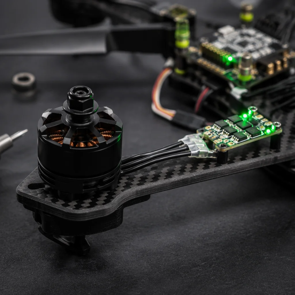
UAV Powertrain Matching
Motor current-to-temperature mapping — the input to the ESC thermal analysis for sustained-load UAV missions.
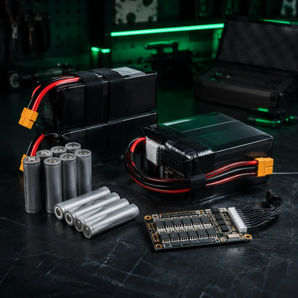
UAV Battery & Power Management
LiPo and Li-Ion discharge thermal behavior — I²R heating, thermal time constant, and pack temperature limits.
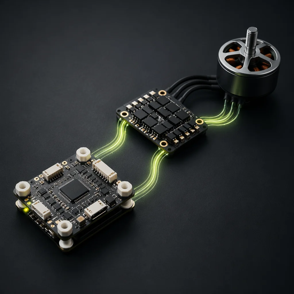
FC & ESC Matching
Electrical compatibility plus thermal de-rating — the two constraints that determine safe operating current.
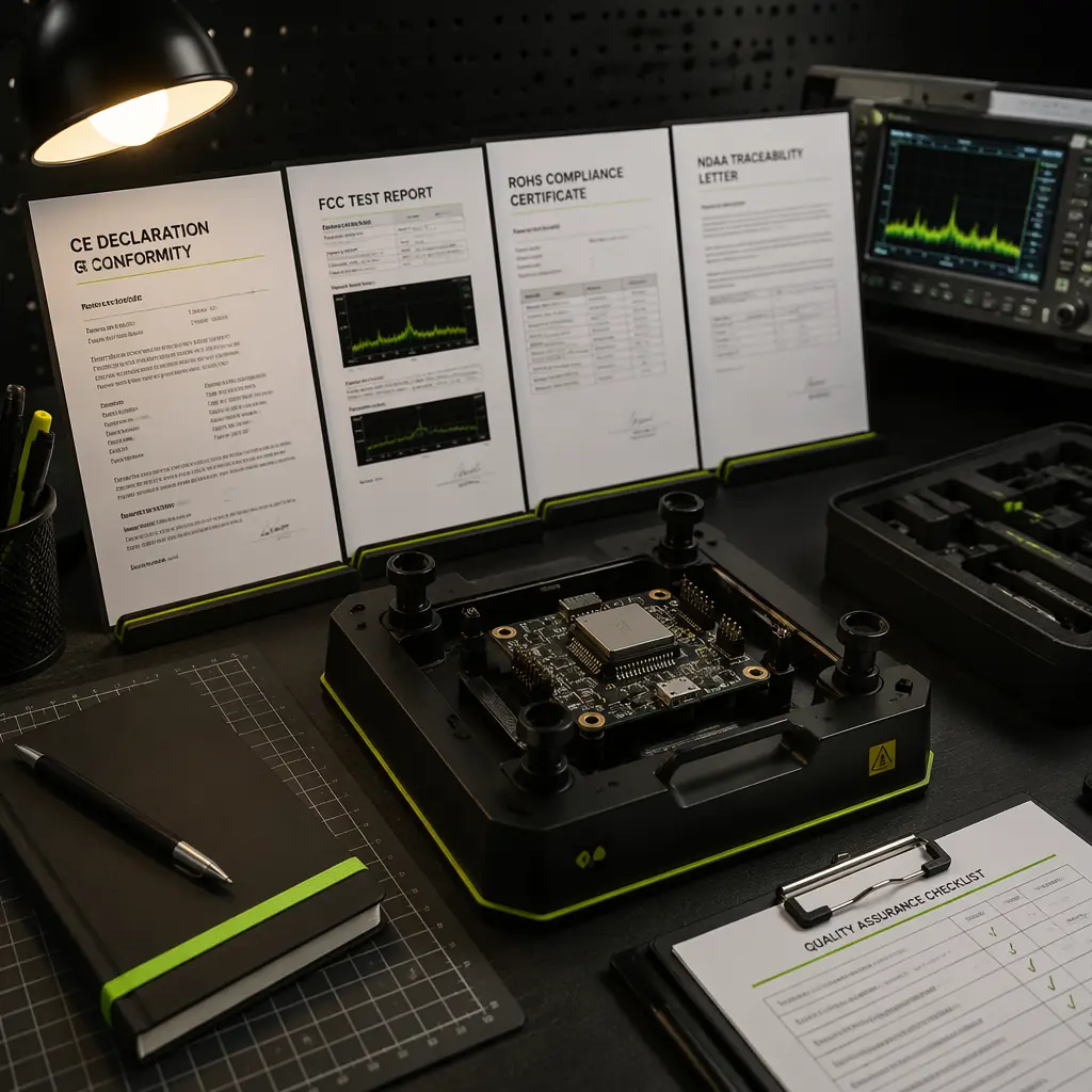
Certification & Compliance Guide
Thermal testing requirements embedded in CE, FCC and ISO 9001 certification for UAV electronics.
UAV Airframe Materials Guide
Thermal conductivity of carbon fiber vs aluminum — choosing the airframe material for conductive heat spreading.