
The defense UAV market has bifurcated into two procurement tiers since 2022. Tier 1 is the program-of-record aircraft — General Atomics MQ-9B, Anduril Ghost, AeroVironment Switchblade — acquired through formal defense acquisition frameworks with component supply chains locked to specific primes and sub-tier manufacturers. Tier 2 is the attritable and tactical ISR segment — small UAVs in the Group 1 and Group 2 classification (under 9 kg and 9–25 kg respectively, per NATO STANAG 4671 taxonomy) — where defense ministries and allied procurement agencies source components from the commercial UAV supply chain but require those components to meet defense-specific hardening, encryption and trade compliance standards that commercial UAVs have no reason to satisfy. As of mid-2026, approximately 60–65% of the global small-UAV defense procurement spend — estimated at USD 4.2 billion in 2025 by the Teal Group — flows through the Tier 2 channel, and the fastest-growing categories within that spend are encrypted C2 data links (28% CAGR), GNSS-denied navigation modules (35% CAGR) and NDAA-compliant propulsion stacks (22% CAGR). The component supply chain that serves this market must bridge two worlds: the cost structure and iteration speed of the commercial UAV ecosystem, and the compliance rigor and environmental survivability of the defense electronics supply base.
The defense UAV component stack has six layers, and the defining characteristic of defense procurement — what separates it from every other UAV application — is that each layer must be specified with an adversary in the loop. The commercial UAV designer asks "will this component perform its function?" The defense UAV procurement team asks "will this component continue to perform its function when a peer adversary is actively trying to prevent it from doing so — by jamming the GPS signal, intercepting the video downlink, targeting the aircraft with small-arms fire, or analyzing the component's semiconductor provenance to identify supply-chain vulnerabilities?" This adversary-in-the-loop mindset changes the specification of every component: the flight controller must navigate without GPS, not just with it; the data link must resist SIGINT collection as well as jamming; the propulsion system must survive not just a single motor failure but the cascade of failures that follows ballistic damage to the airframe; and the entire bill of materials must be traceable to semiconductor foundries and PCB fabrication facilities that are not on an export-denial list. These six layers are not independent — a hardened airframe that adds 200 grams of MIL-STD-810 vibration isolation reduces payload capacity by 200 grams; an AES-256 encryption module that draws 5 watts of additional power reduces hover endurance by 8–12% on a typical 6S lithium-polymer battery. The component architecture must trade survivability against performance against cost, with the adversary's capabilities setting the baseline for all three.
MIL-STD-810 and MIL-STD-461: the defense ruggedization baseline
The two MIL-STD specifications that define the hardware ruggedization surface for defense UAV components are MIL-STD-810H (environmental engineering considerations) and MIL-STD-461G (electromagnetic interference and compatibility). A component that has not been tested to these standards — or to an equivalent national standard such as DEF STAN 00-35 in the UK or AECTP 230 in NATO — has not been demonstrated to survive the environmental and electromagnetic conditions of a tactical deployment. The testing cost for a single component type across the relevant subset of MIL-STD-810H methods typically ranges from USD 15,000 to USD 45,000 at an accredited test laboratory — a cost that the defense UAV integrator must either absorb or verify that the component manufacturer has already absorbed and documented in a test report that can be submitted as part of the procurement package.
MIL-STD-810H: relevant methods for UAV components. Not all 28 methods in MIL-STD-810H are relevant to UAV components. The methods that define the defense UAV ruggedization surface are Method 501.7 (high temperature — operational to +55°C, storage to +71°C, reflecting the interior temperature of a sealed transport container in direct sunlight in a desert theater), Method 502.7 (low temperature — operational to −33°C and storage to −46°C, reflecting Arctic and high-altitude winter operations), Method 507.6 (humidity — 95% relative humidity at +30°C to +60°C for 10 cycles of 48 hours each, reflecting tropical deployment conditions where condensation forms inside electronics enclosures during the day-night thermal cycle), Method 514.8 (vibration — the composite wheeled vehicle spectrum, 5–500 Hz at 1.9 g RMS for 1 hour per axis, reflecting the vibration environment inside a tactical vehicle during cross-country movement), Method 516.8 (shock — 40 g, 11 ms terminal sawtooth pulse, reflecting the shock of a hard landing on unprepared terrain or a transport case drop from 1.2 meters), and Method 510.7 (sand and dust — blowing sand at 18 m/s for 90 minutes and blowing dust at 8.9 m/s with a concentration of 10.6 g/m³ for 6 hours, reflecting desert operating conditions). A flight controller, ESC or communications module that passes these six methods — operational temperature from −33°C to +55°C, 95% humidity cycling, 1.9 g RMS random vibration, 40 g shock, blowing sand and dust — has demonstrated the environmental survivability baseline for defense UAV deployment.
MIL-STD-461G: EMI/EMC for co-located systems. Defense UAVs operate in an electromagnetic environment that is fundamentally different from the commercial environment. A tactical UAV launched from a military vehicle may operate within 2 meters of a 50-watt VHF radio (30–88 MHz), a 20-watt UHF SATCOM terminal (240–320 MHz), an L-band IFF interrogator (1030/1090 MHz) and a C-band fire-control radar (5.2–5.9 GHz). The UAV's electronics must not emit conducted or radiated emissions that interfere with these co-located systems (CE102 for conducted emissions, 10 kHz–10 MHz; RE102 for radiated emissions, 2 MHz–18 GHz for surface ships and submarines, 10 kHz–18 GHz for aircraft), and must continue to operate when exposed to the radiated fields from those co-located systems (RS103, 2 MHz–18 GHz at 20–200 V/m depending on the platform). A UAV component that passes RE102 and RS103 at the aircraft limits — typically 20 V/m from 2 MHz to 18 GHz for a Group 2 UAV operating from a ground vehicle — has demonstrated the electromagnetic compatibility required for co-deployment with tactical communications and sensors. For the communications link specifically, the UAV RF communication systems guide covers the frequency band trade-offs and link budget calculations for contested spectrum environments.
 Concept illustration
Encrypted communications and anti-jamming: the contested spectrum stack
The communications link on a defense UAV is the primary attack surface for an adversary. Jamming the C2 link disables the aircraft; intercepting the video downlink provides the adversary with real-time intelligence on the UAV's ISR collection; spoofing the C2 link enables the adversary to take control of the aircraft. The defense UAV communications architecture must provide three capabilities that commercial UAV data links do not: link-layer encryption that protects both the payload data and the packet metadata (aircraft position, heading, speed) from SIGINT collection; anti-jamming waveforms that maintain a minimum data throughput — typically 0.5–2 Mbps for C2 and a compressed video thumbnail at 1 frame per 2–5 seconds — in the presence of a jammer with 10–20 dB of effective radiated power advantage; and LPI/LPD (Low Probability of Intercept / Low Probability of Detection) waveform characteristics that make the UAV's RF emissions difficult to detect, geolocate and classify by an adversary's electronic support measures (ESM) system.
Link-layer encryption with per-session keying. The minimum encryption standard for defense UAV data links is AES-256 implemented in the radio's baseband processor — the FPGA or ASIC that handles the physical layer modulation, not a general-purpose application processor running a software encryption library. Hardware-level encryption prevents a class of side-channel attacks — timing analysis, power analysis, electromagnetic emanations — that software encryption on a general-purpose processor is vulnerable to. The encryption key must be generated per session using an ECDH (Elliptic Curve Diffie-Hellman) key agreement protocol with a P-256 or Curve25519 elliptic curve, exchanged between the aircraft and the ground control station during the pre-flight pairing handshake, and must never be stored in non-volatile memory on either the aircraft or the ground station — at power-down, the key is erased from volatile memory. The key length must be 256 bits (AES-256), not 128 bits (AES-128), because a 128-bit key is within the theoretical brute-force search capability of a well-resourced adversary with access to ASIC-based key-search hardware — a 256-bit key is not, by a margin of approximately 2^128 (3.4 × 10^38), which exceeds the estimated computational capacity of all computing hardware on Earth combined by more than 20 orders of magnitude.
Anti-jamming architecture: frequency-hopping and spread-spectrum. A narrowband jammer — a continuous-wave transmitter that saturates a single frequency with noise — can disable a fixed-frequency data link with approximately 10 dB of jammer-to-signal (J/S) power advantage. An FHSS (Frequency-Hopping Spread Spectrum) waveform that hops across 50–200 channels at 100–500 hops per second raises the required J/S ratio to approximately 30–40 dB for effective denial — the jammer must either hop in synchronization with the transmitter (which requires breaking the pseudo-random hopping sequence, computationally infeasible if the sequence is generated from the session key) or spread its power across the entire hopping bandwidth (which reduces the jammer power density at any single frequency by a factor equal to the number of channels). An FHSS waveform at 900 MHz or 1.2 GHz with 100+ hopping channels and 100+ hops per second provides effective anti-jamming protection against all but the most sophisticated reactive jammers — a class of jammer that rapidly detects the active frequency and retunes to jam it within a fraction of the hop dwell time. A reactive jammer requires a detection-to-jamming latency under 1 millisecond to be effective against a 100 hops-per-second waveform; achieving this latency across a wide bandwidth requires a digital RF memory (DRFM) architecture that costs USD 50,000–200,000 and is fielded primarily by peer-state electronic warfare units, not by non-state actors.
LPI/LPD waveforms for emissions control. A conventional COFDM waveform at 2.4 GHz with 20 MHz bandwidth and 20 dBm transmit power produces a spectral power density of approximately −53 dBm/Hz at the transmitter output — easily detectable by a spectrum analyzer at ranges of 2–5 km using a simple omnidirectional antenna. An LPI waveform uses direct-sequence spread spectrum (DSSS) with a processing gain of 20–30 dB — spreading a 1 Mbps data stream across a 100–1,000 MHz bandwidth, reducing the spectral power density by the same factor — to push the signal below the noise floor of the adversary's ESM receiver. A DSSS waveform with 30 dB of processing gain at 1.2 GHz, transmitting 1 Mbps across 1 GHz of bandwidth, produces a spectral power density of approximately −113 dBm/Hz at the transmitter output — below the thermal noise floor of −114 dBm/Hz at the receiver — and is undetectable by a spectrum analyzer beyond approximately 100–200 meters unless the analyzer knows the spreading code and can correlate against it. For the RF hardware and antenna architecture that supports these waveforms, the UAV RF communication systems guide covers the power amplifier linearity, antenna gain and front-end filtering requirements for spread-spectrum operation across wide bandwidths.
GNSS-denied navigation: inertial, visual and signals-of-opportunity fusion
GPS jamming is no longer a theoretical threat — it is the default electromagnetic environment in every active conflict zone. Since February 2022, GPS jamming has been documented at scale in Ukraine, where Russian electronic warfare units operating R-330Zh Zhitel and RB-301B Borisoglebsk-2 jammers routinely deny GPS L1 (1575.42 MHz) and L2 (1227.60 MHz) reception across 30–50 km sectors of the front line. A defense UAV that relies on GPS for navigation — even GPS augmented with SBAS or GBAS corrections — is a UAV that will be non-mission-capable in any conflict zone where a peer adversary fields GPS jamming. The defense UAV navigation architecture must provide a GNSS-denied fallback that maintains position accuracy within 2–5% of distance traveled (2–5 meters of accumulated error per 100 meters of flight, or approximately 20–50 meters after 1 km) for at least 10 minutes of GNSS-denied flight — enough time to complete a tactical ISR loiter over a target area and return to a recovery point where GNSS is reacquired.
Inertial navigation: IMU grade and drift rates. The core of GNSS-denied navigation is an inertial measurement unit (IMU) that integrates acceleration and angular rate to estimate position, velocity and attitude. The IMU's position drift rate — the rate at which the position estimate diverges from the true position in the absence of GNSS corrections — is the primary performance metric. A tactical-grade IMU (0.1–1.0 degrees per hour gyro bias stability, 0.05–0.5 mg accelerometer bias stability) drifts at approximately 1–5 meters of position error per minute of GNSS-denied flight when tightly coupled with a barometric altimeter and a magnetometer for heading drift correction. A navigation-grade IMU (0.001–0.01 degrees per hour gyro bias stability) drifts at 0.1–0.5 meters per minute but costs USD 8,000–25,000 and weighs 200–500 grams — prohibitive for a Group 1 or Group 2 UAV. The practical IMU specification for a defense UAV under 25 kg is a tactical-grade MEMS IMU with 0.5–1.0 deg/hr gyro bias stability, coupled with a visual-inertial odometry (VIO) system that uses a downward-facing or forward-facing camera — typically a global-shutter monochrome sensor at 640 × 480 resolution, 60 fps — to track visual features on the terrain and provide velocity corrections to the IMU's integration loop at 20–30 Hz. The VIO-augmented tactical IMU reduces the position drift rate from 2–5 meters per minute to 0.5–1.5 meters per minute — a 3–5× improvement — by providing an independent velocity measurement that bounds the IMU's velocity integration error.
Signals-of-opportunity navigation (SoOP). When GPS is jammed, the RF spectrum still contains dozens of signals with known transmitter locations and precisely controlled carrier frequencies — cellular base stations (4G/LTE at 700–2600 MHz), broadcast television (ATSC at 54–698 MHz in North America, DVB-T at 174–786 MHz in Europe), Iridium and Globalstar satellite communications (1616–1626 MHz and 2483–2500 MHz respectively) and LEO broadband constellations (Starlink, OneWeb at 10.7–12.7 GHz). A software-defined radio (SDR) receiver — typically a small form-factor module weighing 30–80 grams, such as the Ettus USRP B200mini or the Nuand bladeRF 2.0 — can simultaneously receive signals from 5–15 of these transmitters, measure the carrier frequency offset due to Doppler shift (which provides a velocity vector relative to each transmitter) and the time-difference-of-arrival between pairs of transmitters (which provides a position fix via multilateration). A SoOP navigation system with 10+ tracked transmitters achieves position accuracy of 10–50 meters RMS in urban and suburban environments — not GPS-level accuracy, but sufficient to navigate to a recovery point where GPS can be reacquired. The SoOP receiver adds approximately USD 400–1,200 to the UAV's BOM cost and draws 3–5 watts of power — a modest penalty for the assurance of navigation continuity when GPS is denied.
 Concept illustration
Propulsion survivability: motor redundancy and ballistic-tolerant airframes
The propulsion system on a defense UAV must survive damage that a commercial UAV never encounters — small-arms fire, fragmentation from indirect fire (mortars, artillery), collision with obstacles during low-altitude nap-of-the-earth flight, and hard landings on rocky or debris-strewn terrain where a gentle flare to touchdown is not an option. The propulsion survivability requirement translates directly to the motor count: a quadcopter that loses one motor becomes uncontrollable within 0.3–0.5 seconds; a hexacopter that loses one motor maintains stable attitude and executes a controlled descent with the five remaining motors at approximately 120% of their nominal hover thrust; an octocopter that loses one motor continues flying with minimal performance degradation — the seven remaining motors at 114% of nominal thrust, easily within the continuous rating of most 400–600 KV motors at 6S. For defense UAVs, the octocopter is the standard configuration when the mission requires the aircraft to continue ISR collection after taking ballistic damage — the asset (the ISR feed) is more valuable than the platform (the aircraft), and losing both because a single motor was hit by a 7.62 mm round is an unacceptable single point of failure.
Coaxial octocopter for survivability with compact folded size. The conventional octocopter — eight arms radiating from a central hub — has a wheelbase of 1,200–1,400 mm for a 25 kg aircraft, which is too large to fit in the trunk of a standard tactical vehicle (typically 900–1,100 mm of usable width). The coaxial octocopter — four arms, each carrying two motors in a coaxial configuration (one motor above the arm, one below, with counter-rotating propellers) — achieves the same motor-out survivability as a conventional octocopter in the folded size of a quadcopter: four arms that fold to approximately 350 × 350 × 250 mm. The aerodynamic penalty of the coaxial configuration — the lower propeller operates in the downwash of the upper propeller, reducing its efficiency by 15–25% — is offset by the survivability gain of eight independent motor-ESC-propeller channels in a platform that deploys from a standard tactical vehicle. For the motor and propeller sizing methodology that accounts for the coaxial efficiency penalty, the UAV powertrain matching guide covers the thrust curve calculations for single-plane and coaxial motor configurations.
Ballistic-tolerant airframe materials. A carbon fiber tube arm that is struck by a 7.62 × 39 mm round at 90 degrees to the laminate plane will likely be severed — carbon fiber has high tensile strength along the fiber direction but very low interlaminar shear strength, and a ballistic impact delaminates the layers. A hybrid arm construction — a carbon fiber outer tube (for bending stiffness and torsional rigidity) with an aramid fiber (Kevlar or Twaron) inner sleeve (for ballistic tolerance and post-impact structural integrity) — can absorb a single 7.62 mm round strike without complete structural failure: the carbon fiber outer layer may crack and delaminate, but the aramid inner sleeve holds the arm together and maintains the motor's mechanical connection to the central hub, enabling a controlled descent. The aramid sleeve adds approximately 15–25 grams per arm and USD 8–15 per arm to the BOM cost. For the material selection and laminate design methodology, the UAV airframe materials guide covers the stiffness-to-weight and strength-to-weight trade-offs for carbon fiber, aramid and hybrid composite arm constructions.
Export-controlled payloads: ITAR, EAR and the munitions list boundary
The payload on a defense UAV crosses the regulatory boundary between a commercial dual-use item — exportable under the Export Administration Regulations (EAR) with a Commerce Control List (CCL) classification and potentially a license exception — and a defense article controlled under the International Traffic in Arms Regulations (ITAR) with a United States Munitions List (USML) classification requiring a DSP-5 export license. The distinction is defined not by the payload's function but by its specifications: a thermal camera that exports at 9 Hz frame rate (CCL ECCN 6A003.b.4, potentially eligible for license exception STA) becomes ITAR-controlled at 30 Hz frame rate (USML Category XII, specifically XII(c)(9) for "imaging systems specifically designed for military applications with a frame rate greater than 9 Hz"). A laser range-finder with a 1,550 nm wavelength, 5 km range and 2 m accuracy is EAR99 (no export license required) if sold as a surveying instrument; the same laser range-finder integrated into a UAV with a target geo-location function becomes a "fire control system component" under USML Category XII(d). The payload specification determines the export jurisdiction, and the export jurisdiction determines whether the assembled UAV can be shipped to an allied defense ministry without a 6–12 month licensing process.
ITAR/EAR boundary for common UAV payloads. The following payload categories cross the ITAR/EAR boundary at well-defined specification thresholds: thermal cameras (≤9 Hz frame rate = EAR, >9 Hz = ITAR), radiation detectors (energy resolution ≤8% FWHM at 662 keV for Cs-137 = EAR, better resolution or designed for SNM detection = ITAR), and electronic warfare payloads (any device designed to jam, deceive or intercept communications or radar signals = ITAR under USML Category XI). A defense UAV integrator sourcing payloads for an export-controlled system must either select EAR-classified payloads and accept the specification limitations (9 Hz thermal frame rate may be adequate for ISR but inadequate for moving-target tracking), or select ITAR-classified payloads and accept the 6–12 month export licensing cycle and the end-use monitoring obligations that accompany a DSP-5 license. For the sensor integration and mechanical interface standards, the UAV payload integration guide covers the gimbal, vibration isolation and electrical isolation architecture that applies across ITAR and EAR payload categories.
NDAA Section 848 and the trusted supply chain
Section 848 of the National Defense Authorization Act (NDAA) for Fiscal Year 2020 — codified at 10 U.S.C. § 487c — prohibits the U.S. Department of Defense from procuring or operating UAV systems manufactured by entities from covered foreign countries, specifically the People's Republic of China, and from procuring UAV components — flight controllers, ESCs, motors, communications modules, cameras, gimbals, navigation systems and ground control stations — manufactured by entities from covered countries. The practical effect of NDAA Section 848 on the UAV component supply chain is that any component containing a semiconductor manufactured by a PRC-headquartered foundry, or assembled on a PCB fabricated by a PRC-headquartered PCB manufacturer, or containing firmware developed by a PRC-headquartered entity, may render the entire UAV system non-compliant with NDAA — which means it cannot be sold to the U.S. Department of Defense, and by extension to any allied defense ministry (NATO members, Five Eyes partners, and Indo-Pacific allies such as Japan, South Korea and Australia) that aligns its procurement compliance with NDAA standards as a condition of interoperability with U.S. forces.
Component traceability to the foundry level. NDAA compliance for a UAV component requires traceability of every semiconductor device — microcontrollers, FPGAs, IMU MEMS sensors, RF power amplifiers, GNSS receiver chipsets — to the wafer fabrication facility (foundry) that produced the silicon. A component manufacturer that sources an STM32 microcontroller from STMicroelectronics is NDAA-compliant because STMicroelectronics' fabrication facilities are in Europe (France, Italy, Malta) and Singapore. A component manufacturer that sources a GigaDevice GD32 microcontroller — a pin-compatible clone of the STM32, produced by a PRC-headquartered semiconductor company — is not NDAA-compliant, even if the component passes all functional and environmental tests. The traceability requirement extends to the PCB fabrication: a 4-layer or 6-layer PCB fabricated by a PRC-headquartered PCB manufacturer renders the component NDAA-noncompliant, regardless of the semiconductor provenance. The U.S. Defense Innovation Unit (DIU) maintains a Blue UAS Cleared List of UAV components that have passed NDAA compliance verification — as of mid-2026, approximately 35 flight controllers, 20 ESCs and 15 communications modules are on the Cleared List. For the sourcing strategy that balances NDAA compliance with cost, the UAV component build vs. buy framework covers the supply-chain trade-offs for dual-use and defense procurement programs.
 Concept illustration
Procurement checklist: 8 component decisions for defense UAVs
These eight component decisions form the minimum procurement gate for a defense UAV. Each is tied to a specific operational requirement: mission survivability in a denied environment, data link security against a peer adversary's SIGINT capability, and trade compliance with the export control regime of the country of origin.
1. MIL-STD-810H environmental qualification. The flight controller, ESCs and communications module must be tested to Methods 501.7 (high temp +55°C operational), 502.7 (low temp −33°C operational), 507.6 (95% RH humidity cycling), 514.8 (1.9 g RMS random vibration, 1 hour per axis), 516.8 (40 g terminal sawtooth shock) and 510.7 (blowing sand and dust). Validate by requesting the component manufacturer's test reports from an ISO/IEC 17025 accredited laboratory — do not accept a self-declared compliance statement without test data.
2. MIL-STD-461G RE102 and RS103 EMI/EMC. Radiated emissions below the RE102 limit curve for aircraft (10 kHz–18 GHz), radiated susceptibility to 20 V/m from 2 MHz to 18 GHz. Validate by testing the integrated UAV — not just the individual components — with the tactical radios and sensors that will be co-located within 2 meters during deployment.
3. AES-256 link-layer encryption with per-session keying. Encryption implemented in the radio's baseband processor, not in software on an application processor. ECDH key exchange with P-256 or Curve25519, per-session ephemeral keys erased at power-down. Validate by capturing the over-the-air waveform with a spectrum analyzer and confirming that the packet headers — not just the payload — are encrypted.
4. FHSS anti-jamming waveform with 100+ hopping channels. Frequency-hopping at 900 MHz or 1.2 GHz with at least 100 channels and 100+ hops per second, pseudo-random sequence generated from the session key. Validate by testing against a broadband noise jammer at 20 dB J/S ratio: the C2 link must maintain connectivity, and the video downlink must maintain at least 1 frame per 2 seconds.
5. GNSS-denied navigation with tactical-grade IMU and VIO. MEMS IMU with 0.5–1.0 deg/hr gyro bias stability, global-shutter camera for visual-inertial odometry, barometric altimeter. Validate by flying a 1 km closed-loop course with GPS disabled: the final position error at the recovery point must be ≤50 meters (5% of distance traveled).
6. Octocopter propulsion with independent ESC fusing. Eight motors with per-ESC current-limiting, motor-failure detection at the flight controller within one control loop cycle. Validate by disabling two motors — one on each of two different arms — in flight: the aircraft must maintain stable attitude and execute a controlled descent. For the motor and propeller matching, see the powertrain matching guide.
7. ITAR/EAR payload jurisdiction determination. Every sensor on the payload — thermal camera, laser range-finder, radiation detector, SIGINT receiver — must have a written export jurisdiction determination (CCL ECCN classification for EAR items, USML category for ITAR items) from the component manufacturer or from an export control attorney. Validate by requesting the jurisdiction determination document and verifying that the specified frame rate, resolution, sensitivity and wavelength match the actual component specifications.
8. NDAA Section 848 semiconductor and PCB traceability. Every semiconductor — microcontroller, FPGA, IMU, GNSS receiver, RF power amplifier — must be traceable to the wafer fabrication facility, and every PCB must be traceable to the fabrication facility. Validate by requesting the component manufacturer's NDAA compliance letter, which must list the semiconductor part numbers, the foundry name and location for each, and the PCB fabrication facility name and location. For the broader procurement strategy, see the supplier evaluation checklist and the supply chain layers guide.
Explore custom engineering Back to Blog
Continue Reading
UAV RF Communication Systems
AES-256 encrypted data links, dual-band redundancy and anti-jamming architectures for contested spectrum operations.
UAV Payload Integration Guide
ITAR/EAR payload classification, gimbal integration and export-controlled sensor interface standards for defense UAVs.

Supplier Evaluation Checklist
10-point component supplier audit framework including NDAA compliance verification and foundry traceability.

UAV Supply Chain Layers
How the defense UAV component supply chain connects Tier-1 integrators to semiconductor foundries.
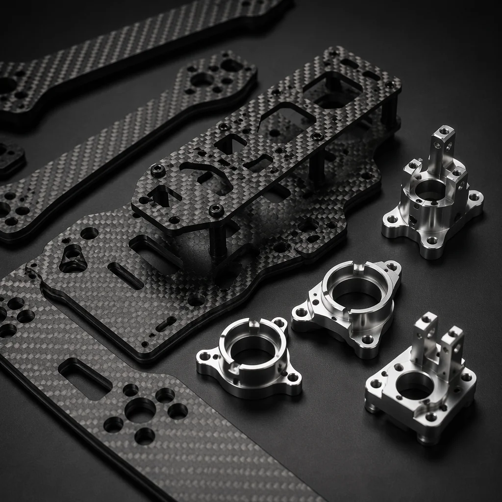
Airframe Materials Guide
Carbon fiber-aramid hybrid arm design for ballistic tolerance and post-impact structural integrity.