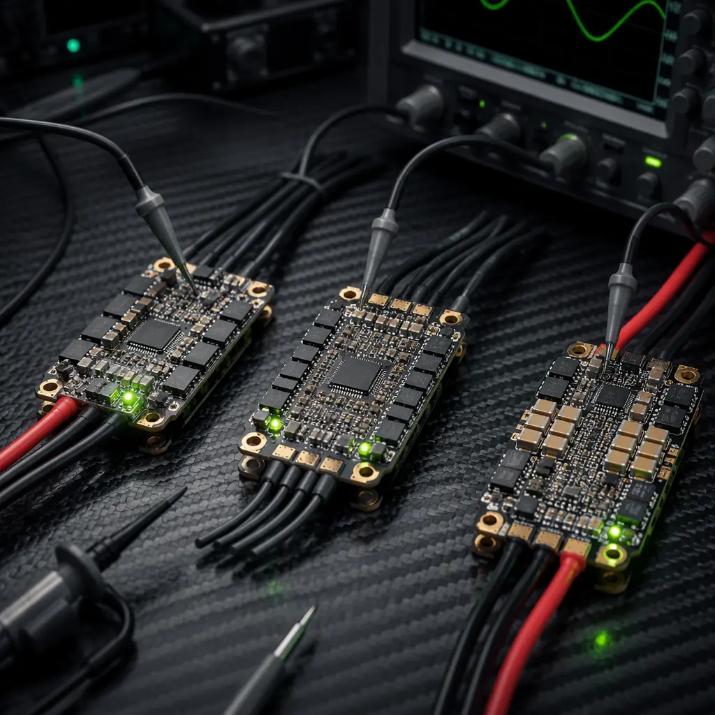
The electronic speed controller is the bridge between the flight controller's logic and the motor's physics. A flight controller running ArduPilot at a 1 kHz control loop can compute a new throttle setpoint every millisecond — but whether the ESC actually delivers that setpoint with microsecond-level precision, or smooths it through a 50 ms ramp, depends entirely on the firmware running on the ESC's microcontroller. Procurement teams that treat ESCs as interchangeable 40 A or 80 A black boxes are making a system-level architecture decision by omission.
This article assumes familiarity with the flight controller and ESC matching fundamentals covered in the FC/ESC matching guide — voltage architecture, current headroom, and the distinction between PWM, DShot and CAN bus control protocols. The firmware selection discussed here applies to ESCs that already support at least DShot 300 or CAN FD, which are the minimum control interfaces for industrial UAV applications where telemetry feedback and fault detection are non-negotiable. For the broader powertrain context, the UAV powertrain matching guide covers how firmware choice interacts with motor KV rating and propeller load matching.
The three firmware ecosystems: what they are and where they came from
Three open firmware platforms dominate the industrial UAV ESC landscape. Each emerged from a different design philosophy, and each carries architectural assumptions that influence everything from startup behavior to failure mode response.
BLHeli_32. Developed as a closed-source 32-bit successor to the widely used BLHeli_S firmware, BLHeli_32 runs on STM32 or AT32 microcontrollers and provides a configuration interface through BLHeliSuite32. It supports standard protocols including DShot 150/300/600/1200, Oneshot42/125, Multishot and standard PWM input. The firmware's signature strength is its bidirectional DShot capability — the ESC reports motor electrical RPM back to the flight controller at the DShot frame rate, enabling the flight controller to run RPM-based notch filtering that suppresses frame resonance without a separate tachometer. This is particularly valuable on carbon fiber airframes where motor vibrations couple into the IMU through the frame structure, reducing the control loop's effective bandwidth. For airframe coupling considerations, the airframe materials guide explains how structural stiffness affects vibration transmission paths.
BLHeli_32's limitations stem from its closed-source nature. The firmware binary is supplied by the ESC manufacturer and cannot be modified by the integrator. Parameter configuration covers approximately 40 settings including timing advance, demag compensation, PWM frequency and temperature protection thresholds, but the underlying control algorithm — the actual commutation logic — is a black box. This is acceptable for platforms where the ESC operates well within its rated envelope, but becomes a liability when the integrator needs to tune commutation timing for a specific motor-propeller combination operating near the thermal limit.
AM32. AM32 is the open-source answer to BLHeli_32, built from the ground up with a GPLv3 license and designed to run on the same STM32F051 and AT32F415 hardware that BLHeli_32 targets. The firmware stack is fully inspectable and modifiable — an integrator can change commutation timing algorithms, adjust the startup sequence for large-diameter propellers with high rotational inertia, or add custom telemetry fields to the DShot response frame. AM32 supports DShot 300/600/1200, bidirectional DShot, and standard PWM input. The configuration tool is an open-source web application that communicates over USB through a standard serial passthrough from an ArduPilot or Betaflight flight controller.
The open-source advantage is most visible at the edges of the operating envelope. When a 32-inch propeller driven by a 100 KV motor takes 2.5 seconds to spin up from zero to hover RPM, the ESC's startup ramp algorithm — how it detects rotor position at standstill and transitions from open-loop forced commutation to closed-loop back-EMF sensing — determines whether the motor starts smoothly or oscillates violently. With AM32, the integrator can inspect and modify this algorithm. With BLHeli_32, the integrator adjusts timing advance and hopes the black-box algorithm handles it. For build-vs-buy sourcing decisions involving firmware customization, the UAV component build vs buy framework applies directly to the decision of whether to invest in custom AM32 tuning versus accepting BLHeli_32's factory defaults.
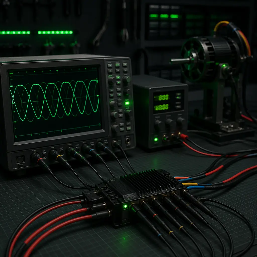
FOC (Field-Oriented Control). FOC represents a fundamental departure from the trapezoidal commutation used by both BLHeli_32 and AM32. In trapezoidal commutation — sometimes called six-step commutation — the ESC energizes two of the three motor phases at any instant, with the third phase floating. The rotor position is estimated from the back-EMF zero-crossing on the floating phase. This works well at medium to high speeds where back-EMF is strong, but produces torque ripple and audible noise at low speeds, and loses rotor position tracking entirely at very low speeds where back-EMF is too weak to detect.
FOC replaces this with sinusoidal commutation: all three phases are energized simultaneously with sinusoidal currents that create a smoothly rotating magnetic field. The rotor position is tracked continuously using either hall sensors, an encoder, or a sensorless observer algorithm that estimates position from phase current and voltage measurements at a rate of 20–50 kHz. The result is near-zero torque ripple at any speed, silent operation, and the ability to hold position at zero speed — a capability that trapezoidal ESCs simply do not have. FOC ESCs also support regenerative braking as a native operating mode rather than an add-on, recovering kinetic energy during descent and feeding it back into the battery. For heavy-lift platforms operating in the 12S–14S voltage range discussed in the UAV battery and power management guide, regenerative braking during controlled descent can extend flight time by 3–8% depending on the descent profile.
 Concept illustration
Decision framework: matching firmware to mission profile
The firmware decision should be driven by the mission profile's demands on throttle response, efficiency, telemetry granularity and fault tolerance. The following framework maps mission types to the firmware architecture that best serves them.
High-maneuverability multirotors: BLHeli_32 or AM32. Platforms that need rapid throttle response — inspection drones maneuvering around infrastructure, cinematography platforms tracking fast-moving subjects, or first-responder drones changing altitude aggressively — benefit from the low-latency trapezoidal commutation used by BLHeli_32 and AM32. The throttle signal-to-motor-RPM path in a DShot 1200 configuration takes approximately 1.2 ms from flight controller output to motor current change. FOC adds approximately 0.5–1.0 ms of additional latency from the observer algorithm's filtering, which is negligible for cruise flight but noticeable during aggressive maneuvering. BLHeli_32's closed-source firmware is adequate here because the ESC operates within its rated current envelope and does not require custom commutation tuning. The RPM filter capability from bidirectional DShot is the primary value-add for these platforms. For the full powertrain matching context including the motor and propeller side, the powertrain matching guide provides the sizing calculations.
Long-endurance mapping and survey: FOC. Mapping platforms that fly grid patterns at 40–55% throttle for 45–90 minutes gain the most from FOC's efficiency advantage. FOC reduces copper losses by approximately 5–12% compared to trapezoidal commutation at partial throttle, because the sinusoidal current waveform produces lower RMS current for the same torque output. On a platform drawing 1,800 W in cruise, a 7% efficiency gain translates to roughly 125 W saved — roughly 5–8 minutes of additional flight time on a 1,500 Wh battery pack. FOC's silent operation is a secondary benefit for surveying in noise-sensitive environments, and the ability to hold position at zero speed with active braking removes the need for a separate parking brake on the gimbal or payload. For platform-specific component selection, the mapping and survey components guide covers GNSS, camera and airframe integration that complement the propulsion choices discussed here.
Heavy-lift and cargo platforms: FOC with regenerative braking. Platforms carrying 5–15 kg payloads for logistics, agriculture spraying or sensor delivery operate in a regime where descent energy recovery is material. A 25 kg platform descending from 120 m at 2 m/s takes 60 seconds to land, during which the potential energy dissipation rate is approximately 25 kg × 9.81 m/s² × 2 m/s = 490 W. A FOC ESC with regenerative braking can recover 60–70% of this energy — roughly 300 W for 60 seconds, or 5 Wh per descent. Over 20 sorties per day, that is 100 Wh recovered, enough to extend the daily operational window by one additional flight or reduce the battery capacity requirement by approximately 5%. For heavy-lift airframe integration including mounting, vibration isolation and cooling airflow for the ESC modules, the airframe materials guide covers structural considerations that affect ESC placement and thermal management. The supplier qualification process for FOC ESCs follows the same framework as the UAV supplier evaluation checklist, with additional emphasis on the ESC manufacturer's firmware update cadence and field-reported failure modes.
Flight controller compatibility: ArduPilot, PX4 and the protocol layer
The firmware running on the ESC must be compatible with the flight controller's output protocol. This compatibility is not optional — mismatching firmware capability with FC output protocol produces anything from reduced telemetry to complete motor failure at startup.
ArduPilot. ArduPilot's DShot implementation supports DShot 150/300/600/1200 with bidirectional DShot for RPM feedback on firmware versions 4.1 and later. The bidirectional DShot telemetry is native to BLHeli_32 (firmware version 32.7 and later) and AM32 (version 1.90 and later). FOC ESCs typically communicate over CAN bus rather than DShot, using the DroneCAN protocol — ArduPilot supports DroneCAN natively and can receive per-ESC telemetry including phase current, MOSFET temperature, motor RPM, and cumulative energy consumption. The CAN bus architecture allows daisy-chaining multiple ESCs on a single two-wire bus, reducing wiring complexity on platforms with 6–8 motors. For the communication infrastructure that supports CAN bus telemetry alongside the primary RF data link, the RF communication systems guide covers frequency band selection and interference management.
PX4. PX4's DShot support is similar to ArduPilot's, with bidirectional DShot available from PX4 v1.13. PX4's DroneCAN stack is more mature than ArduPilot's — PX4 was the reference platform for DroneCAN development — and provides ESC firmware update capability over the CAN bus, allowing fleet-wide firmware rollouts without physically connecting to each ESC's USB port. PX4's actuator configuration framework separates the control allocation (which motor gets what signal) from the ESC protocol (DShot vs CAN vs PWM), making it easier to mix different ESC firmware types on the same airframe — for example, FOC ESCs on the main lift motors with BLHeli_32 ESCs on a tail rotor or auxiliary thruster.
 Concept illustration
Telemetry: what each firmware tells you — and what it does not
Telemetry is where the firmware architectures diverge most sharply, and it is the dimension that has the greatest operational impact on fleet management. A failed ESC that provides no telemetry is indistinguishable from a broken propeller until the aircraft's attitude begins to diverge. An ESC that reports MOSFET temperature rising from 65°C to 85°C over three consecutive flights tells the operator to inspect airflow before the fourth flight cooks the output stage.
BLHeli_32 telemetry over bidirectional DShot provides motor electrical RPM (eRPM) at the DShot frame rate — typically 8 kHz on DShot 600 or 16 kHz on DShot 1200. The flight controller uses this for RPM filtering, but the raw eRPM value is also available to the ground control station through MAVLink telemetry. BLHeli_32 also reports a single temperature value, which is typically the temperature at the microcontroller's internal sensor rather than at the MOSFETs where the real thermal stress occurs. Current and voltage are estimated rather than measured — the firmware infers current from the electrical RPM and timing advance rather than from a shunt resistor — making BLHeli_32's power telemetry indicative rather than metering-grade.
AM32 telemetry provides the same eRPM and temperature fields as BLHeli_32, but the open-source architecture allows integrators to add custom telemetry fields. A common modification adds per-phase current sensing through external shunt amplifiers, reporting actual phase current rather than estimated current. This is significant for platforms that push ESCs near their thermal limits: estimated current can be off by 15–30% under partial-throttle conditions where the relationship between RPM and torque is nonlinear, while shunt-measured current is accurate to within 2–5%. For procurement teams evaluating ESC suppliers, the difference between estimated and measured telemetry is a key quality signal — discussed further in the supplier evaluation checklist.
FOC telemetry over DroneCAN is the richest of the three architectures. A DroneCAN-connected FOC ESC reports per-phase current (typically ±2% accuracy through low-side shunt sensing), MOSFET temperature at each half-bridge (three temperature sensors per ESC), DC bus voltage, motor RPM, cumulative watt-hours consumed, and a fault register that distinguishes between over-current, over-temperature, desync, and phase-loss events. The cumulative energy consumption field is particularly valuable for fleet operations: after 200 flight hours on a pack, the operator can compare actual Wh consumed against the battery's rated capacity to detect capacity fade before it causes an in-flight low-battery event.
 Concept illustration
Thermal behavior: why firmware determines ESC operating temperature
Two ESCs with identical MOSFET ratings and identical heatsinking can differ in operating temperature by 15–25°C depending on firmware architecture. The difference is not component quality — it is how the firmware drives the MOSFETs.
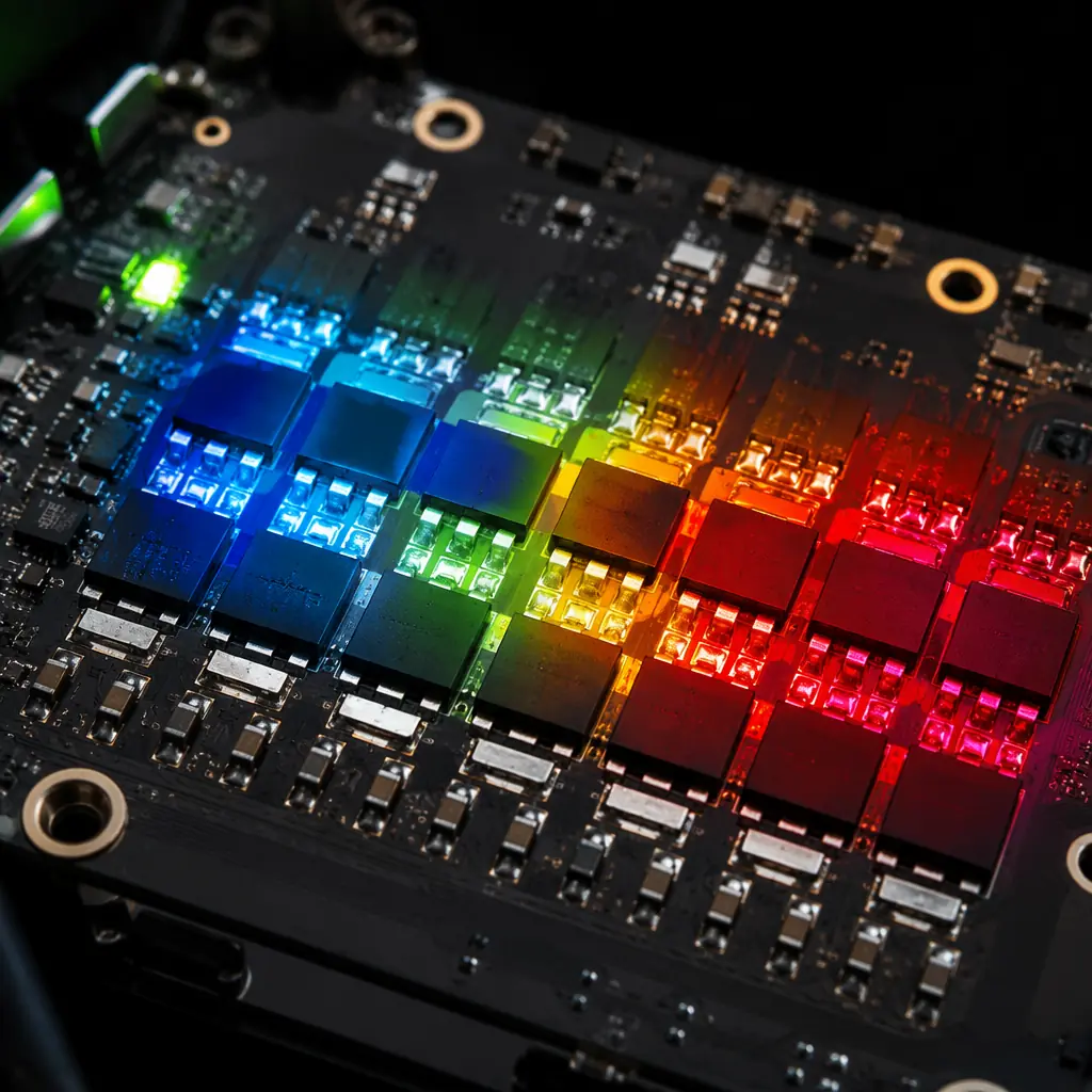
In trapezoidal commutation, each MOSFET switches at the motor's electrical frequency multiplied by the PWM carrier frequency. For a 14-pole motor running at 6,000 RPM, the electrical frequency is 700 Hz, and with a 24 kHz PWM carrier, each MOSFET switches approximately 24,000 times per second. Every switching transition dissipates energy proportional to the DC bus voltage, the current being switched, and the MOSFET's gate charge. FOC reduces switching losses through space-vector modulation, which arranges the switching sequence to minimize the number of transitions per electrical cycle — typically reducing switching losses by 10–20% compared to standard center-aligned PWM used by BLHeli_32 and AM32.
The practical consequence: a 40 A ESC running BLHeli_32 at 30 A continuous on a 6S system operates the MOSFETs at approximately 80–90°C junction temperature with adequate airflow. The same ESC running FOC at the same current operates at approximately 65–75°C — a 15°C reduction that approximately doubles the MOSFET's expected lifetime according to the Arrhenius aging model. For platforms operating in high-ambient-temperature environments — agricultural spraying at 38°C, industrial inspection near hot equipment — the thermal margin provided by FOC can be the difference between reliable operation and thermal shutdown. For the power system architecture that determines operating voltage and current levels, the battery and power management guide provides the upstream sizing context.
 Concept illustration
Procurement checklist: 5 questions to ask any ESC supplier
When evaluating ESCs for an industrial UAV program, the following five questions separate commodity suppliers from engineering-grade vendors. Suppliers that cannot answer these questions with specific data points — not marketing language — should be treated as black-box resellers rather than integration partners.
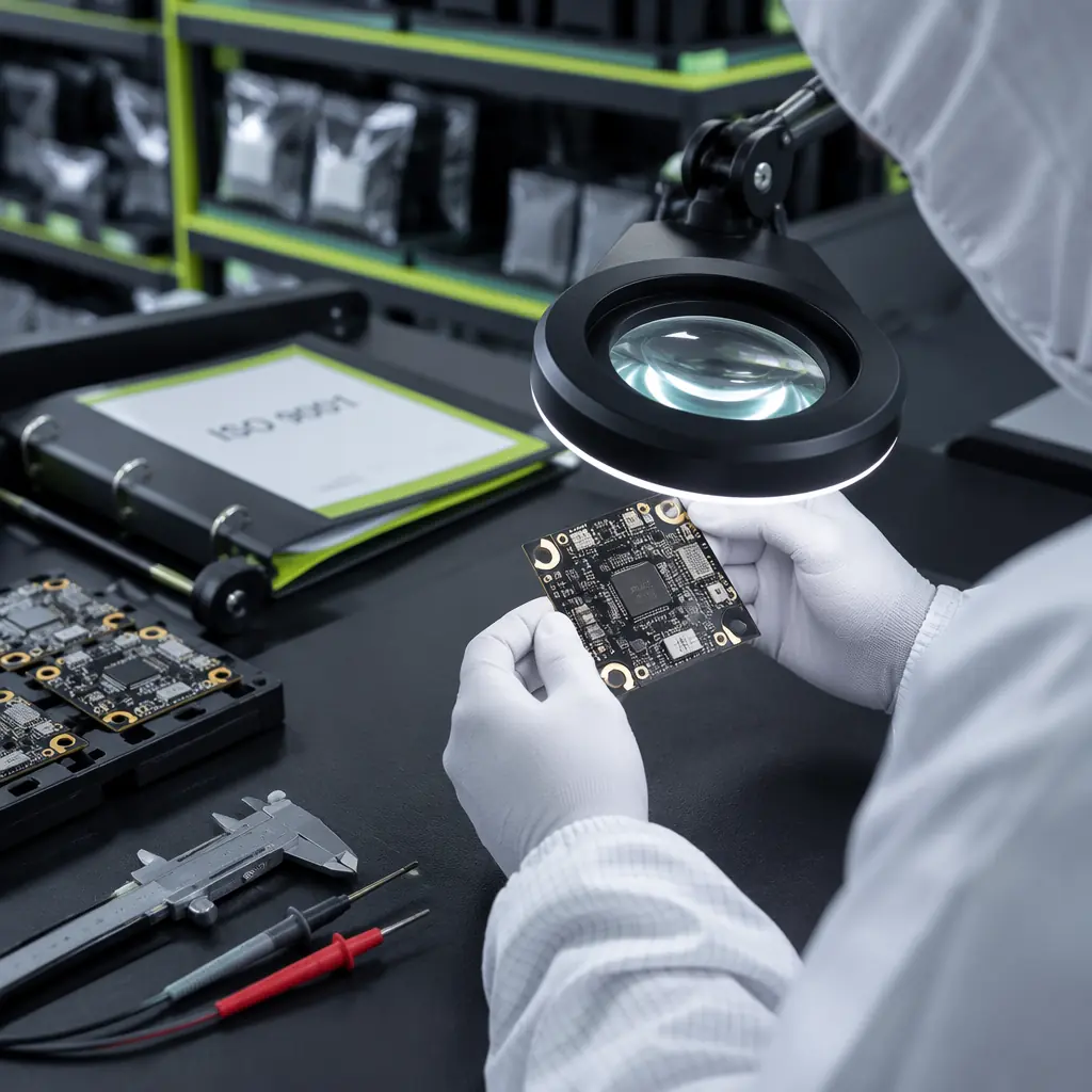
1. Which firmware build and version ships on the ESC? The answer should include the specific version number (e.g., AM32 v1.96, not "latest AM32"), the build date, and the configuration file that defines the default parameter set. An ESC with firmware from 2023 may lack critical fixes for desync recovery or bidirectional DShot timing that were added in 2024–2025 builds. The supplier should commit to flashing the latest stable build before shipment upon request, and should provide a change log of firmware modifications if they maintain their own fork.
2. What is the telemetry accuracy specification? For current measurement, the answer should be a percentage of full-scale reading (e.g., ±3% at 50 A full scale). For temperature, it should specify sensor placement — MCU die temperature versus MOSFET case temperature, and whether the sensor is on the high-side or low-side MOSFETs which typically run 5–10°C hotter than the high-side. Estimated values should be explicitly labeled as estimates, not measurements. The component testing and qualification framework in the supplier evaluation checklist provides the full evaluation protocol for verifying these claims.
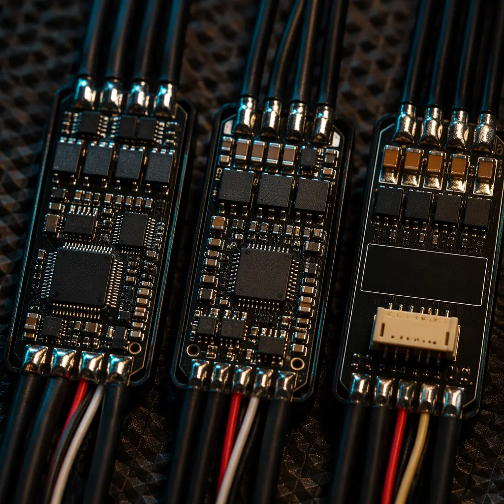
3. What is the desync recovery behavior? A desync occurs when the ESC loses rotor position tracking — typically during rapid throttle changes, propeller strikes, or when a motor bearing seizes. The recovery behavior differs by firmware: BLHeli_32 typically attempts a restart within 500 ms after detecting zero back-EMF; AM32 allows configuring the restart attempt count and delay; FOC can detect desync within one electrical cycle and re-establish position tracking without a full restart. The supplier should provide oscilloscope captures showing the phase current waveform during a commanded desync-and-recovery sequence. Without this data, the ESC's behavior during a real desync at altitude is unknown.
4. What is the CAN bus / DShot protocol latency specification? For DShot ESCs, the latency from the falling edge of the DShot frame to the start of the corresponding PWM cycle should be specified in microseconds, with both typical and worst-case values. For CAN bus ESCs on DroneCAN, the message latency should be specified under both idle and saturated bus conditions (80% bus load). This matters because the flight controller's control loop assumes a known actuator latency — ArduPilot uses a configurable delay parameter — and an ESC with 2 ms typical latency and 8 ms worst-case latency creates an unmodeled 6 ms jitter in the control loop that degrades attitude tracking performance.
5. Can we flash our own firmware build? For AM32 and open-source FOC firmware, the answer should be yes — the ESC should expose a standard SWD (Serial Wire Debug) header or support firmware upload over CAN bus using the DroneCAN bootloader protocol. For BLHeli_32, the answer is no by design — but the supplier should commit to providing firmware updates for the supported lifetime of the product. An ESC that ships with firmware that can never be updated is a single-point-of-failure in the supply chain: if a firmware bug is discovered after deployment, the only remediation is replacing every ESC in the fleet.
Explore ESC & power systems Back to Blog
Continue Reading
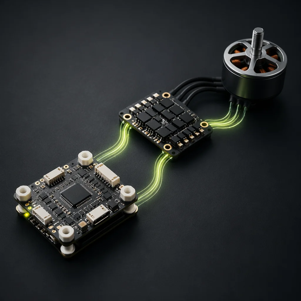
FC & ESC Matching
Voltage architecture, current headroom and protocol selection — the hardware layer that firmware runs on.
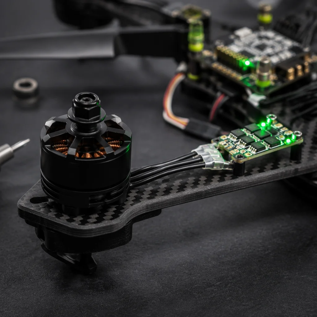
UAV Powertrain Matching
Motor KV, propeller sizing and how the full propulsion stack fits together.
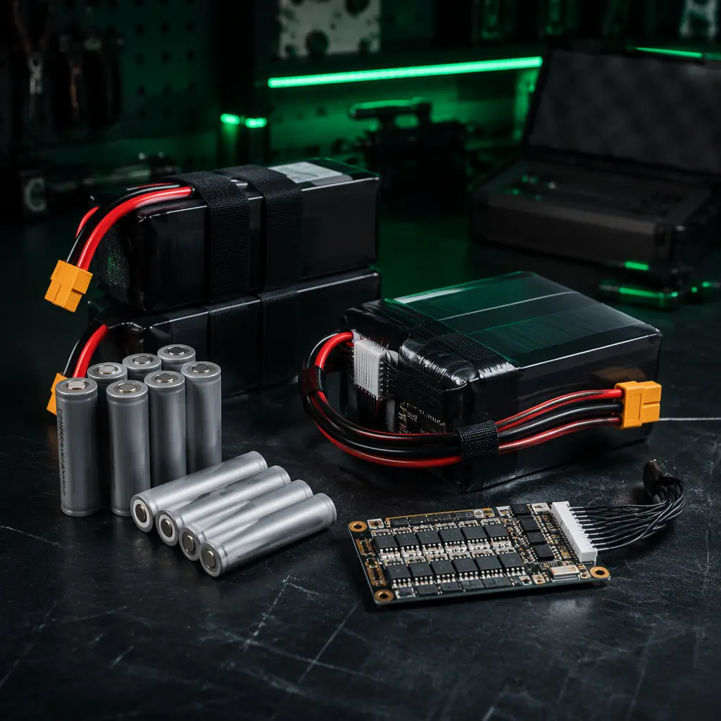
Battery & Power Management
LiPo vs Li-Ion chemistry and how voltage architecture constrains ESC selection.
Supplier Evaluation Checklist
How to qualify ESC manufacturers and verify their technical claims.
Build vs Buy Sourcing
Whether to source commodity ESCs or commission custom firmware tuning.