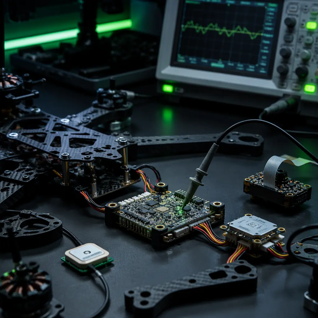
Academic and industrial R&D programs account for approximately 35–40% of the professional UAV component market by unit volume — a share that is often underestimated because research procurement is distributed across hundreds of university labs, government research institutes and corporate R&D divisions, each buying 2–10 units per year rather than the 50–500 unit fleet purchases that characterize commercial operations. As of mid-2026, the global academic UAV research community publishes approximately 4,500 peer-reviewed papers per year involving custom UAV platforms — spanning robotics (SLAM, path planning, swarm control), environmental science (atmospheric sampling, wildlife monitoring), agricultural engineering (precision spraying, crop phenotyping), computer vision (aerial object detection, 3D reconstruction) and mechanical engineering (novel airframe configurations, propulsion efficiency). Each of these research programs needs a component stack that does not impose a fixed architecture — the flight controller must accept custom control laws, the sensor payload must expose raw data at the native sample rate without onboard filtering, the airframe must accommodate non-standard payload geometries, and the entire stack must be reconfigurable in hours, not weeks, because a PhD student's experiment that works on Monday may need a different sensor on Tuesday and a different propulsion configuration on Wednesday.
The R&D component procurement challenge is structural rather than technical. Commercial UAV platforms are optimized for a specific mission — a mapping UAV carries a specific camera at a specific altitude at a specific speed — and the flight controller, airframe and power system are co-optimized for that mission profile. A research UAV, by contrast, is optimized for flexibility: the same airframe must carry a multispectral camera on Monday, a gas sampling payload on Tuesday and a novel LIDAR-inertial odometry sensor on Wednesday, each with different mass, power draw, center-of-gravity offset and data interface requirements. The component stack must provide standardized mechanical, electrical and data interfaces that decouple the payload from the platform — so that changing the payload does not require changing the flight controller parameters, re-tuning the PID loops or rebuilding the airframe. This guide covers the five layers of the research UAV component stack: the flight controller with its software development kit and parameter exposure, the modular airframe with its payload attachment system, the sensor payload interface with its electrical and data standards, the telemetry and data logging system for research-grade data integrity, and the power system for the extended ground-test and flight-test cycles that characterize R&D workflows.
Open-architecture flight controllers: PX4 and ArduPilot for research workflows
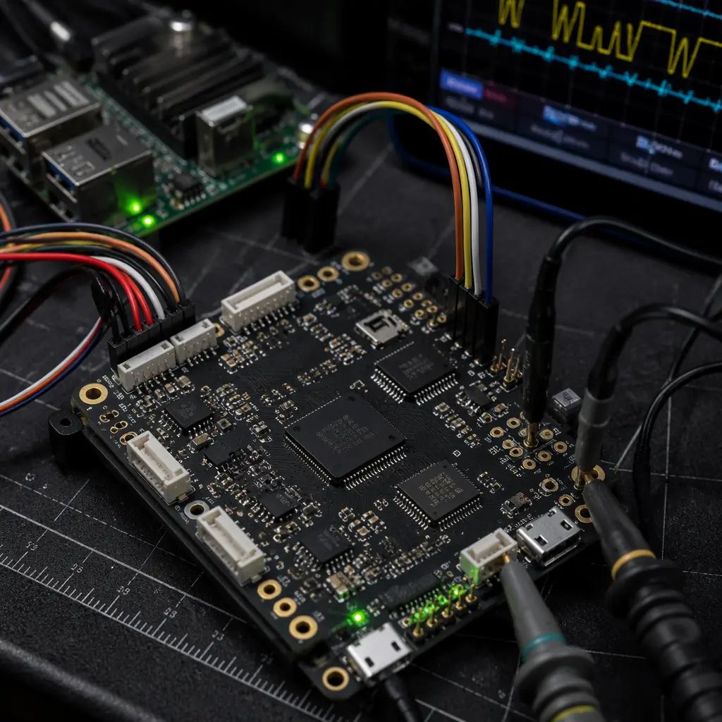
The flight controller is the central decision point for a research UAV program — and the decision between PX4 and ArduPilot is not about flight performance (both achieve ±0.5 meter position hold with RTK GNSS at 10 Hz and <1° attitude accuracy at 8 kHz IMU update rate) but about the software architecture and the research workflow it enables. PX4 runs a real-time operating system (NuttX) with a publish-subscribe message bus (uORB) that allows any research module — a custom attitude controller, a novel sensor fusion algorithm, a swarm coordination protocol — to subscribe to any sensor topic (IMU, GNSS, magnetometer, barometer, optical flow, distance sensor) at the native update rate of that sensor, process the data, and publish its output back to the bus where the actuators subscribe. This is the architecture that a robotics lab expects: a modular software stack where the researcher replaces one module (e.g., the attitude controller) without touching the rest of the stack (sensor drivers, state estimator, position controller, mixer, ESC drivers). ArduPilot runs a single-threaded scheduler with a fixed 400 Hz main loop — simpler to understand and debug, but the researcher who wants to add a computationally expensive custom module (e.g., a nonlinear model predictive controller running at 50 Hz) must ensure it completes within the 2.5 ms time budget of the main loop, which constrains algorithm complexity.
PX4 for robotics and control systems research. The PX4 ecosystem provides three integration points for research code. First, the uORB message bus: the researcher writes a C++ module that subscribes to vehicle_attitude, vehicle_local_position and sensor_combined topics, processes the data with a custom algorithm, and publishes to actuator_controls — the module is compiled alongside the PX4 firmware and runs as a separate NuttX task with its own stack and scheduling priority, isolated from the core flight stack. Second, the ROS 2 bridge (px4_ros_com): the flight controller publishes all uORB topics to ROS 2 topics over a serial link (921,600 baud over UART or USB) or Ethernet (UDP at up to 100 Mbps on a companion computer), and the researcher writes ROS 2 nodes in C++ or Python that process the data on a companion computer (Raspberry Pi 4/5, NVIDIA Jetson Orin, Intel NUC) — this is the standard architecture for computer vision and machine learning research where the algorithm needs a GPU or runs in Python. Third, the Gazebo/HITL simulation bridge: the same PX4 firmware binary that runs on the flight controller hardware runs identically in the Gazebo simulator with software-in-the-loop (SITL), so the researcher develops and tests the custom control algorithm in simulation for 100 hours of simulated flight time, then flashes the same firmware binary — with the custom module compiled in — to the flight controller hardware and flies with zero code changes. For the hardware integration details, the flight controller and ESC matching guide covers the CAN FD and DShot protocol architectures that enable per-ESC telemetry for research-grade propulsion data.
ArduPilot for field science and rapid deployment research. ArduPilot's advantage for research is its mission scripting language — Lua scripts that run on the flight controller at up to 50 Hz, with access to all sensor data and the ability to command the aircraft's position, velocity, attitude and payload triggers. An environmental science team studying atmospheric aerosol distribution writes a Lua script that commands the aircraft to fly a vertical spiral (0–120 meters altitude at 2 m/s vertical speed) while triggering the aerosol sampler at 10-meter altitude increments, logging the GNSS position and barometric altitude at each trigger — a research mission that requires zero modification to the flight controller firmware. ArduPilot's parameter system exposes approximately 700 tunable parameters — PID gains for rate and attitude control, filter cutoff frequencies for the IMU notch filters, navigation acceleration limits, landing speed, geofence behavior — all accessible in real time through the MAVLink protocol and the ground control station. For a research team comparing the flight performance of three different airframe configurations (quadcopter, hexacopter, octocopter) with the same payload, the parameter file is exported from one configuration and imported to the next, so the only variable is the airframe. For the propulsion matching methodology, the UAV powertrain matching guide covers the thrust curve, propeller sizing and motor KV selection that enable a single parameter file to fly across multiple airframe configurations.
 Concept illustration
Modular airframes for rapid prototyping and configuration iteration
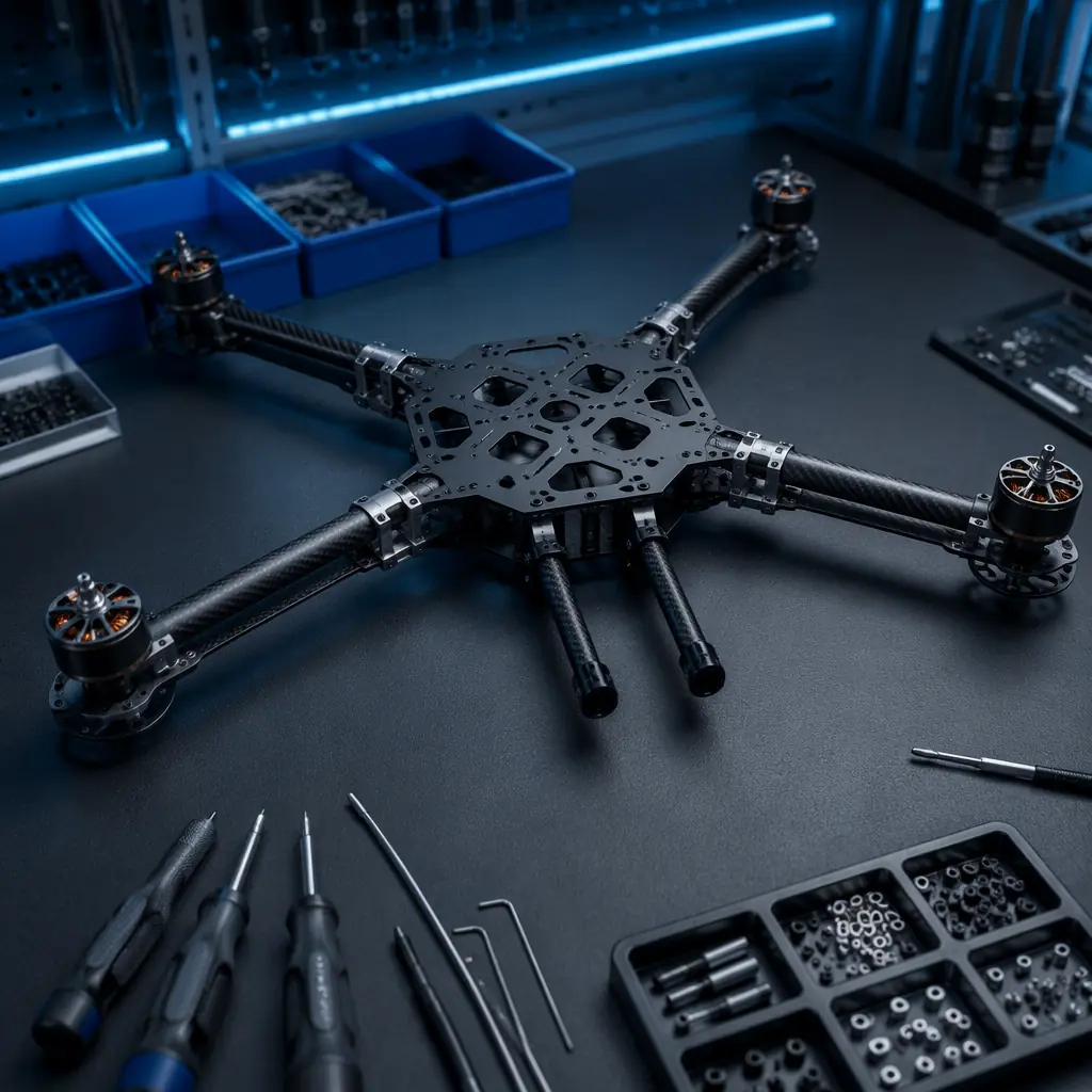
The airframe is the component that changes most frequently during an R&D program — and the airframe architecture must accommodate that churn without requiring new procurement for every configuration change. A modular airframe is defined by three design features: a central hub that accepts multiple arm configurations (quad, hexa, octo, coaxial, X8) through a standardized arm-mount interface, a payload rail or plate system that accommodates non-standard sensor geometries without drilling new mounting holes, and a quick-disconnect wiring system that allows the propulsion system to be reconfigured without re-soldering. The central hub — typically a machined aluminum or injection-molded nylon plate with a 20 × 20 mm or 30 × 30 mm grid of M3 threaded inserts at 10 mm spacing — provides the mounting surface for the flight controller, companion computer, power distribution board, GNSS module, telemetry radio and battery tray, all on a single rigid plate that isolates the electronics from airframe flex. The arm-mount interface uses two M4 bolts per arm through a 25 mm diameter carbon fiber tube clamp — the same clamp works for 450 mm arms (quadcopter, 900 mm wheelbase), 550 mm arms (hexacopter, 1,100 mm wheelbase) or 650 mm arms (octocopter, 1,300 mm wheelbase), so the research team converts from a quad to a hexa by adding two arms, two motors, two ESCs and two propellers — approximately USD 200–300 in additional components and 30 minutes of assembly time — rather than buying an entirely new airframe.
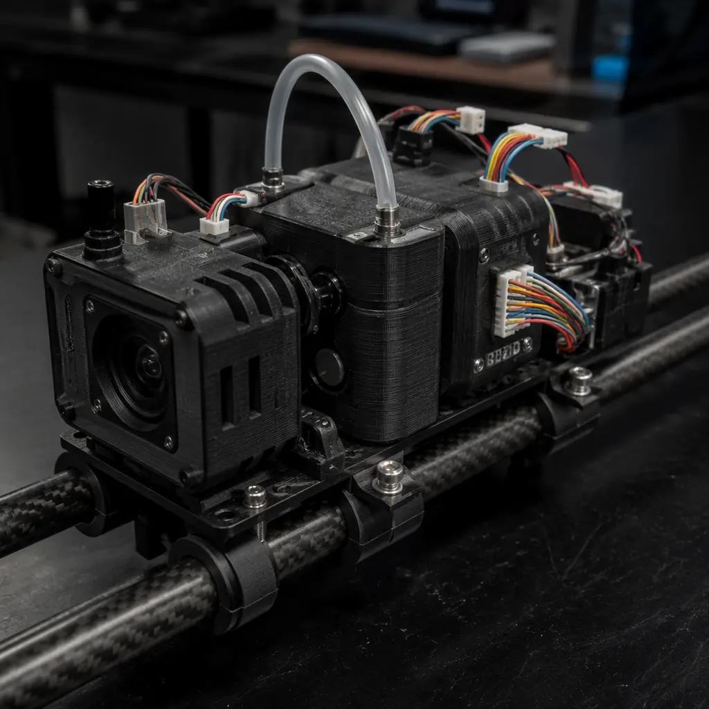
Payload attachment standardization. The payload mounting system on a research UAV must accept sensors that were never designed for UAV integration — a gas analyzer that expects to sit on a laboratory bench, a hyperspectral camera in a weather-sealed industrial enclosure, a custom 3D-printed sensor housing that a PhD student designed in SolidWorks last week. The standard is a dual 10 mm diameter carbon fiber rail system — the same rail spacing used in cinematography camera rigs — mounted to the underside of the central hub with four M4 bolts. Any payload that can be attached to a pair of 10 mm rails with rail clamps (USD 3–5 per clamp, rated for 15 kg clamping force) is mechanically integrated in under 5 minutes. The rails extend 300–400 mm forward of the aircraft center of gravity, providing mounting positions that allow the payload to be shifted fore-aft to balance the center of gravity without adding ballast weight. The rail system also isolates the payload from the airframe vibration: the rail clamps include a 2 mm silicone rubber bushing between the clamp and the rail, which attenuates motor vibration (typically 150–250 Hz at hover RPM for a 400–600 KV motor at 6S) by approximately 15–20 dB before it reaches the payload — adequate for most optical sensors and sufficient that a MEMS IMU on the payload does not saturate from motor vibration. For the carbon fiber and aluminum structural material selection, the airframe materials guide covers the stiffness-to-weight ratios and fatigue life of the tube, plate and clamp components.
 Concept illustration
Configurable sensor payloads with open data interfaces
The sensor payload on a research UAV is not a fixed product — it is an experimental apparatus, and the component stack must treat it as such. The electrical interface standard for research payloads is a regulated power supply with configurable voltage output (5V, 12V, battery voltage pass-through at 6S/22.2V nominal) through a 6-pin JST-GH or Molex Micro-Fit connector that also carries a UART (TX/RX at up to 921,600 baud), I²C (400 kHz) and two general-purpose I/O lines for trigger and status signals — all on a single connector that the researcher mates with a matching connector on the payload side. This standardized payload interface means the researcher develops the payload on a bench power supply and a USB-to-UART adapter, then connects it to the UAV with one connector — no soldering at the field, no adapting voltage levels with a breadboard, no running separate wires for power and data.
Data interface philosophy: raw data, not pre-processed output. A commercial sensor designed for operational UAV use — an NDVI camera for agricultural monitoring, a thermal camera for industrial inspection — applies onboard processing to convert the raw sensor data into a final product: the NDVI camera outputs a georeferenced NDVI map in GeoTIFF format, and the thermal camera outputs a radiometric JPEG with temperature values embedded in the metadata. A research sensor must output the raw data — the individual pixel values from the multispectral sensor before the NDVI calculation, the raw thermal radiometric values before the color-mapping — because the researcher's algorithm may use a different NDVI formula (accounting for atmospheric correction, or using a different red-edge band), or the researcher may be studying the sensor itself rather than using it as a measurement tool. The payload interface specification must therefore require a "raw data mode" where the sensor outputs unprocessed data at the native sample rate, and the UAV's companion computer or onboard logger records it alongside the GNSS and attitude data for post-flight processing. For the mechanical and vibration isolation requirements, the UAV payload integration guide covers the gimbal interfaces, vibration damping and EMI shielding standards.
 Concept illustration
Telemetry and data logging for research-grade data integrity
A research UAV generates data that must survive peer review — and peer reviewers will ask about the data's temporal accuracy (was the GNSS timestamp synchronized across all sensors?), spatial accuracy (was the GNSS position corrected for the lever arm between the antenna and the sensor?), and completeness (were any sensor readings dropped or corrupted during the flight?). The telemetry and logging architecture must provide answers to these questions with hardware-level guarantees, not post-flight assumptions.
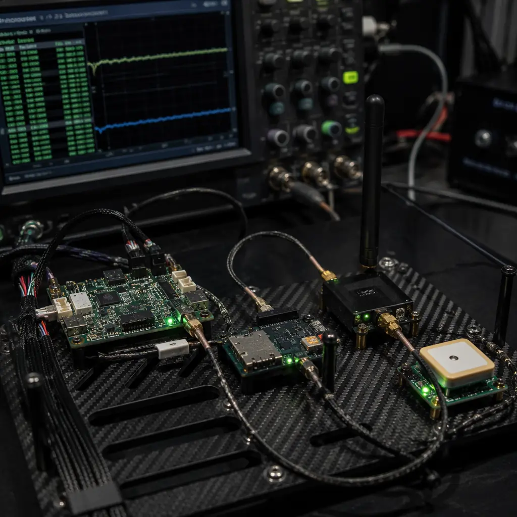
Time synchronization across sensor nodes. The flight controller's GNSS module provides a pulse-per-second (PPS) signal — a TTL-level pulse with a rising edge aligned to the GPS second boundary with ±50 nanosecond accuracy — and a time-of-week message over UART. When the companion computer, the sensor payload and the telemetry radio each connect to this PPS signal and listen for the time-of-week message, all four devices share a common time reference with sub-microsecond synchronization. Each sensor reading is timestamped at the moment of acquisition — not the moment it arrives at the logger — and the logger records the acquisition timestamp alongside the sensor value, the GNSS position, the aircraft attitude and the system health flags (battery voltage, motor RPM, ESC temperature, radio link quality). The log file is written in ULog format (PX4) or DataFlash format (ArduPilot) — both binary formats with per-message CRC-16 checksums — and the logger verifies the checksum of each message before writing it to the SD card, so a corrupted message is detected and flagged rather than silently written with corrupted data.
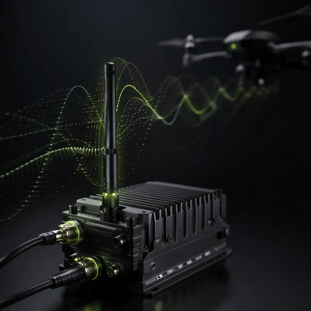
Data throughput and storage. A research UAV with a 20 Hz GNSS+IMU log, a 10 Hz attitude log, a 50 Hz payload sensor log (e.g., a gas analyzer sampling at 50 Hz) and a 1 Hz system health log generates approximately 15–25 MB of log data per flight hour. A 32 GB microSD card (industrial temperature range, UHS-I U3 speed class, ≤USD 15) stores approximately 1,200–2,000 flight hours of log data — effectively unlimited for a research program. The companion computer (Raspberry Pi 4 with a 128 GB SSD) provides an additional logging target for high-bandwidth sensors: a 1080p video stream at 30 fps generates approximately 2–4 GB per flight hour, and the SSD stores 30–60 flight hours. For the data link architecture that transmits telemetry and commands between the aircraft and the ground station, the UAV RF communication systems guide covers the frequency band trade-offs, antenna patterns and link budget calculations.
 Concept illustration
Power systems for extended ground-test and flight operations
An R&D UAV spends more time powered on the ground — in bench testing, sensor calibration, parameter tuning, HITL simulation and pre-flight checks — than it spends in the air. A typical research flight of 20 minutes is preceded by 90–180 minutes of ground power-on time: 30 minutes of sensor warm-up and calibration, 45 minutes of parameter verification and pre-flight checklists, and 15 minutes of post-flight data download and system inspection. The power system must therefore be designed for ground operation — providing regulated power to the flight controller, companion computer, sensor payload and telemetry radio from a bench power supply during ground testing, and transitioning seamlessly to battery power for flight without rebooting any component.
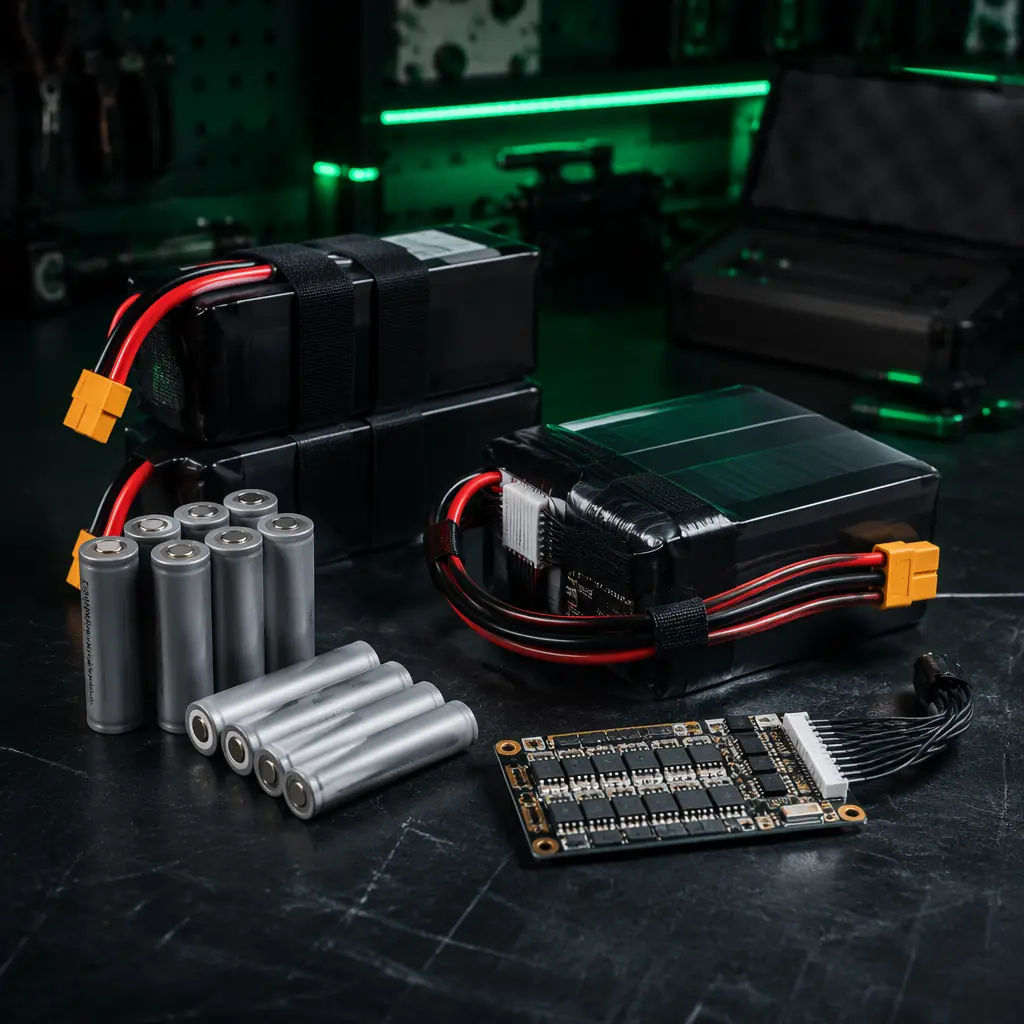
Dual power input architecture. The power distribution board (PDB) on a research UAV must accept two power inputs — a battery input (6S LiPo, 22.2V nominal, up to 16,000 mAh for extended flight) and a bench power input (24V DC, 10A, from a laboratory power supply) — with automatic switching or an ideal-diode OR-ing circuit that prevents the bench supply from back-feeding into the battery. The bench power input allows unlimited ground operation: the researcher leaves the UAV powered on the bench for 3 hours of sensor calibration without consuming battery cycles. The battery chemistry selection — LiPo vs. Li-Ion — is research-dependent: LiPo provides higher discharge current (25–50C continuous, 2–4× the hover current, enabling aggressive maneuvers for control systems research) while Li-Ion provides higher energy density (200–250 Wh/kg vs. 150–180 Wh/kg for LiPo) for extended endurance (60–90 minute flights for environmental monitoring research). The 6S configuration (22.2V nominal) is the standard for UAVs in the 5–15 kg takeoff weight class because it provides adequate voltage headroom for 400–600 KV motors swinging 14–18 inch propellers, and the 6S battery ecosystem — chargers, connectors, parallel charging boards — is standardized across the hobby and professional UAV markets. For the full battery selection methodology, the UAV battery and power management guide covers the LiPo vs. Li-Ion trade-off, cell configuration and discharge curve implications.
Sourcing strategy: low-MOQ procurement for R&D programs
Research procurement is structurally different from commercial fleet procurement: the quantities are small (2–5 units per component type), the specifications change between purchases (the second airframe may need different arm lengths than the first), the budget is grant-funded and must be spent within a fiscal year, and the procurement officer — typically a university purchasing department — needs a quote with a formal invoice, not a shopping cart checkout. A component supplier that serves the R&D market must accept single-unit orders for standard components (motors, ESCs, propellers, carbon fiber tubes, connectors), provide a formal quotation with a proforma invoice for the purchasing department, ship internationally with all required customs documentation (HS code 8807.30 for UAV parts, commercial invoice with declared value), and provide engineering support — answering technical questions about component compatibility, reviewing a researcher's component list for obvious mismatches, and suggesting alternatives when a specified component is out of stock or discontinued.
Component sourcing checklist for research programs. These seven checks define whether a component supplier is R&D-compatible or fleet-only. (1) Single-unit MOQ on standard components — motors, ESCs, propellers, carbon fiber tubes, connectors, cables — no minimum order quantity that forces the lab to buy 10 units when it needs 2. (2) Formal quotation with proforma invoice within 48 hours of the request — the purchasing department needs a PDF with the supplier's company name, address, tax ID, itemized line items with unit prices, shipping cost and total. (3) International shipping with door-to-door tracking — DHL, FedEx or UPS with a tracking number that the researcher can forward to the purchasing department. (4) Engineering review of the component list — the supplier's engineer reviews the list for compatibility issues (e.g., 400 KV motors with 10-inch propellers at 6S, which would produce inadequate thrust) and flags mismatches before the order ships. (5) Technical documentation — motor thrust curves at multiple voltages with propeller specifications, ESC firmware compatibility, flight controller wiring diagrams. (6) Replacement parts availability — spare arms, motor bearings, propeller sets, landing gear — that can be ordered in single units as needed, not only in bulk kits. (7) Confidentiality — the component list and the research application are treated as confidential, not shared or published. For the full supplier evaluation framework, the UAV component supplier evaluation checklist covers the qualification criteria for B2B component procurement.
Explore custom engineering Back to Blog
Continue Reading
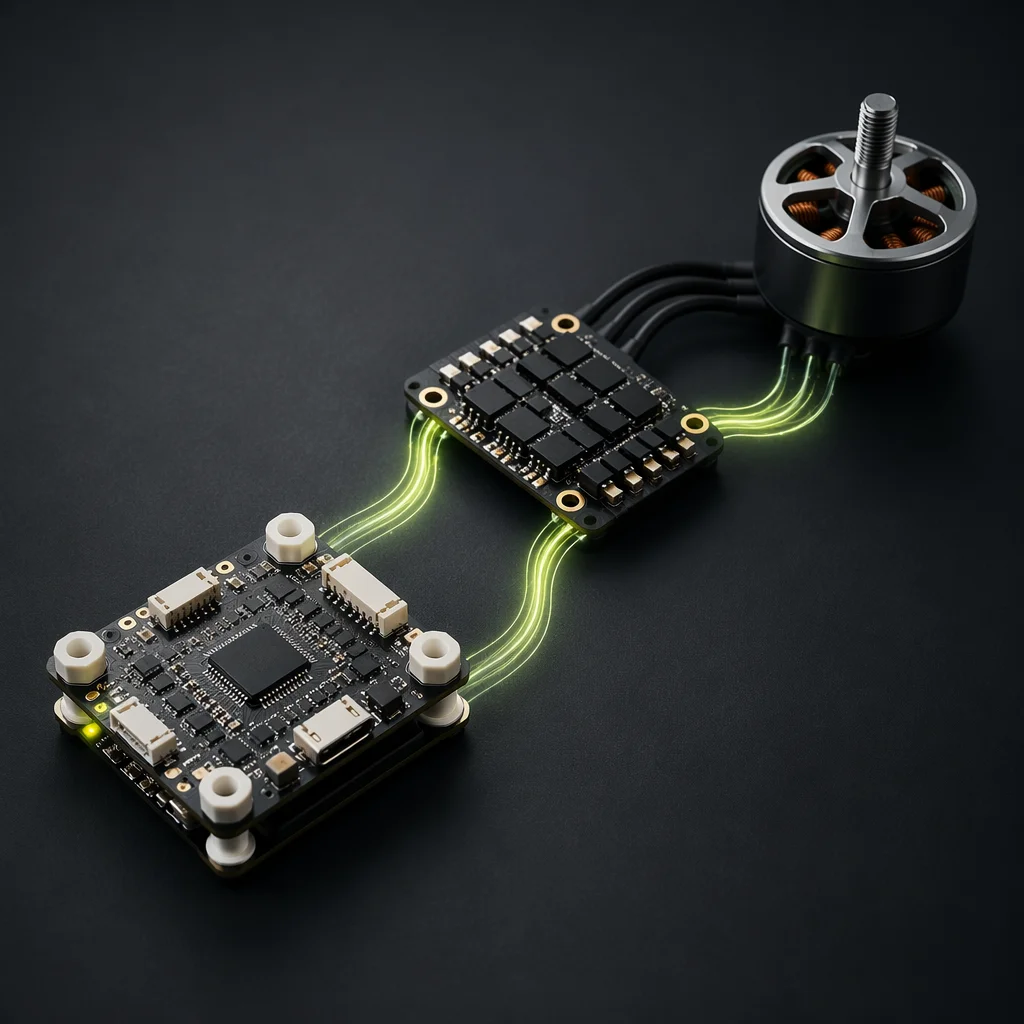
Flight Controller & ESC Matching
CAN FD and DShot protocol architectures, per-ESC telemetry and PID tuning for research-grade flight control.
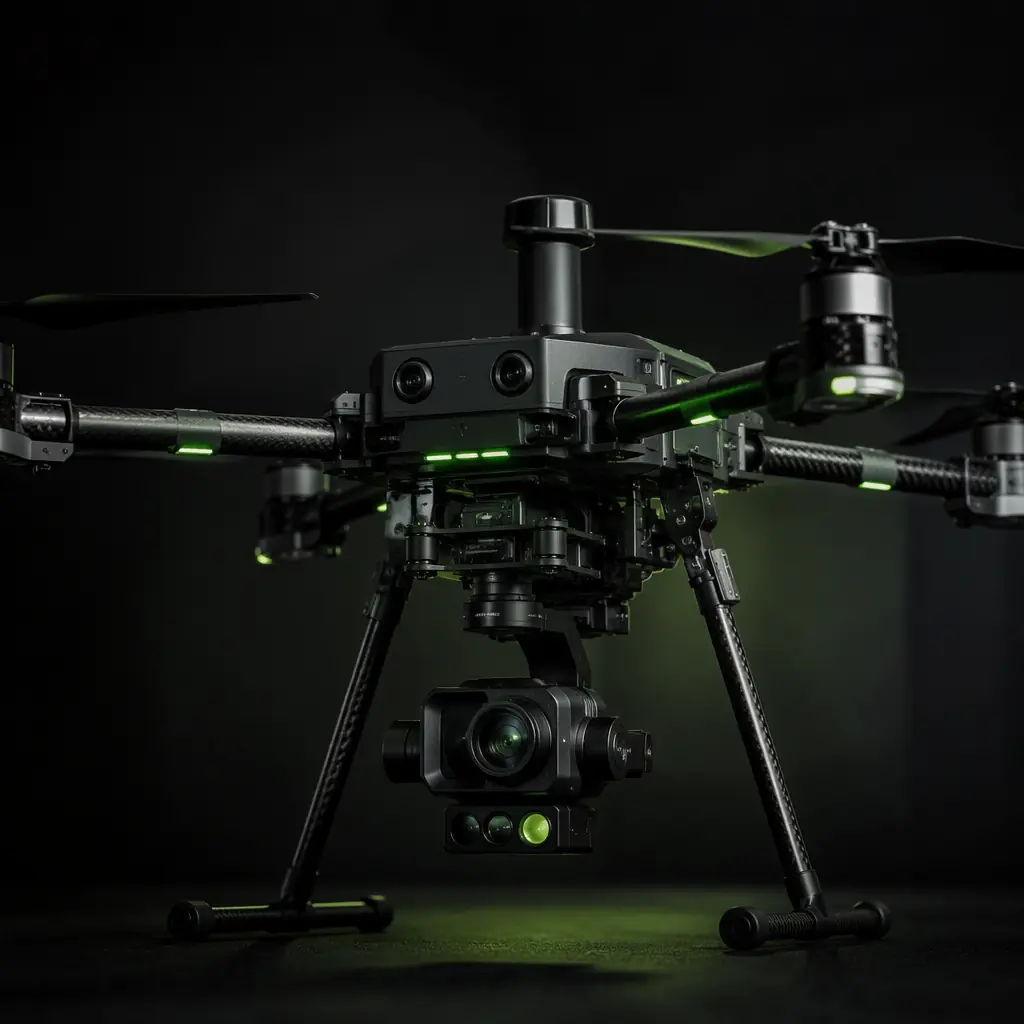
UAV Payload Integration Guide
Gimbal interfaces, vibration isolation and EMI shielding for configurable research sensor payloads.
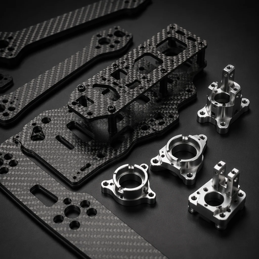
Airframe Materials Guide
Carbon fiber vs. aluminum tube selection, modular clamp durability and fatigue life for prototype airframes.
Battery & Power Management
LiPo vs. Li-Ion chemistry selection, dual power input architecture and bench supply integration for extended ground testing.
UAV RF Communication Systems
Telemetry radio selection, frequency band trade-offs and link budget for research data downlink.