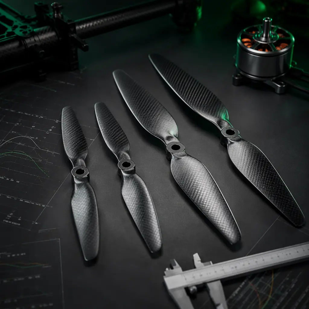
When a UAV integrator reports that a new propulsion configuration is "running hot," the investigation almost always starts at the motor and ESC — measuring winding temperature with an IR thermometer, logging ESC current telemetry, checking PWM timing. In roughly 40% of these investigations, the motor and ESC are operating within their rated specifications, and the root cause is the propeller: the diameter is too large for the motor KV at the operating voltage, the pitch is too aggressive for the airspeed regime, or the blade count pushes the total disk loading beyond what the motor's stator volume can sustain at the target flight time. The propeller is not an accessory bolted onto the end of the powertrain — it is the load that defines the entire electrical operating point, and selecting it without reference to the motor KV curve, the battery sag characteristic and the ESC current headroom is the single most common integration failure in industrial UAV propulsion systems.
The procurement dimension of propeller selection is equally important and frequently overlooked. A propeller is a wear item — it accumulates leading-edge erosion from particulate impact, micro-cracks from vibration fatigue, and UV degradation of the resin matrix in composite blades. A UAV platform with a 2,000-hour design life will consume 4 to 8 sets of propellers over its operational lifespan, compared to zero motor replacements and zero ESC replacements in a properly matched powertrain. The propeller procurement budget, amortized over the platform lifecycle, can exceed the one-time cost of the motors and ESCs combined. Selecting a propeller that is optimized for the mission profile, procurable at the required volume with consistent quality from lot to lot, and maintainable in the field with the tools and skills available to the operator — that is not a catalog browsing exercise. It is a reliability engineering decision with direct impact on platform availability, operating cost per flight hour and component procurement lead time. The UAV powertrain matching framework covers the motor-ESC-voltage integration logic that is the upstream input to propeller selection; this article focuses specifically on the propeller as the final — and mission-defining — element in that chain.
Propeller diameter: the primary thrust driver and the motor current constraint
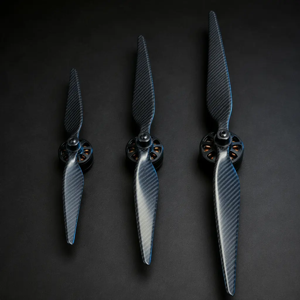
Propeller diameter — measured tip-to-tip across the disk — is the single parameter with the largest effect on static thrust. For a given RPM and pitch, thrust scales approximately with the fourth power of diameter in static conditions: a 15-inch propeller produces roughly 2.4 times the static thrust of a 12-inch propeller at the same RPM, assuming both are operating in the same aerodynamic regime. This is why increasing diameter is the most efficient way to increase payload capacity — at the cost of proportionally higher current draw, which must be accommodated by the ESC current rating, the motor winding gauge and the battery discharge capability.
The diameter constraint is set by three independent limits: the airframe clearance (the physical envelope available between the propeller tip and the nearest structural element — frame arm, payload mount, landing gear — which must maintain at least 25 mm tip clearance at maximum RPM to avoid acoustic coupling and vortex-induced vibration), the motor's maximum continuous current rating at the operating voltage (a 15-inch propeller on a 400 KV motor at 6S will draw approximately 18–24 A at hover thrust for a 5 kg multirotor; the same propeller on a 580 KV motor at 6S will draw 35–45 A because the higher RPM increases the aerodynamic power demand by the cube of the RPM ratio), and the ESC's burst current headroom (the current spike during a rapid climb or gust recovery can exceed the hover current by 40–60%, and the ESC must sustain this without triggering over-current protection or thermal throttling).
 Concept illustration
For procurement, the diameter decision translates into a specific part number with a tolerance specification. A propeller listed as "15×5.5" (15-inch diameter, 5.5-inch pitch) should have a measured diameter within ±0.5% of nominal — 14.925 to 15.075 inches — across a production lot. Diameter variation beyond this tolerance indicates inconsistent mold fill in injection-molded nylon propellers or inconsistent layup compression in carbon fiber propellers, both of which produce blade-to-blade mass imbalance that translates into vibration at the motor bearing. A procurement specification for industrial UAV propellers should include a balance grade: G6.3 per ISO 21940-11 is the minimum acceptable for UAV motors operating above 5,000 RPM; G2.5 is preferred for precision applications such as photogrammetry and LiDAR survey where vibration-induced IMU noise degrades point cloud accuracy.
Pitch: converting rotational speed into forward airspeed
Pitch is the theoretical distance the propeller would advance through the air in one complete revolution if it were moving through a solid medium — measured in inches per revolution. A 15×5 propeller advances 5 inches per revolution; a 15×8 advances 8 inches. Higher pitch produces higher forward airspeed at a given RPM but requires more torque from the motor, and at low airspeeds — hover, vertical climb at low rate — a high-pitch propeller operates at a high angle of attack where the blade is partially stalled, reducing efficiency and increasing current draw without a proportional thrust increase.
The pitch selection logic follows the mission airspeed profile. A multirotor that spends 90% of its flight time in hover or near-hover — inspection of stationary infrastructure, precision agriculture spot-spraying, construction site progress monitoring — should use a pitch-to-diameter ratio of approximately 0.35:1 to 0.40:1. A 15-inch propeller for a hover-dominated mission would be a 15×5.5 or 15×6. A multirotor that spends a significant portion of its flight time in forward flight at 15–25 m/s — linear infrastructure inspection (power line, pipeline, railway), mapping grid coverage, delivery — should use a pitch-to-diameter ratio of 0.45:1 to 0.55:1. A 15-inch propeller for a forward-flight-dominated mission would be a 15×7 or 15×8. A fixed-wing UAV, where the propeller operates almost entirely in forward flight at airspeeds of 18–35 m/s, should use a pitch-to-diameter ratio of 0.55:1 to 0.75:1 — a 15×10 or 15×12.
| Mission Type | Flight Regime | Pitch/Diameter Ratio | Example (15" base) | Typical Efficiency (g/W) |
|---|---|---|---|---|
| Inspection / Monitoring | Hover-dominant (0–5 m/s) | 0.35–0.40 | 15×5.5 | 8.5–10.5 |
| Mapping / Survey | Forward cruise (12–18 m/s) | 0.40–0.50 | 15×6.5 | 7.5–9.5 |
| Delivery / Logistics | Mixed (hover + 15–22 m/s) | 0.45–0.55 | 15×7 | 7.0–8.5 |
| Fixed-wing Cruise | Forward only (18–35 m/s) | 0.55–0.75 | 15×10 | 6.0–7.5 |
These efficiency ranges represent typical values for carbon fiber propellers at sea level, 25°C ambient, with a well-matched motor operating at 65–75% of its maximum continuous current. Efficiency drops at higher altitudes (approximately 3% per 1,000 m due to reduced air density, which reduces thrust for a given RPM and forces the motor to spin faster to maintain the same lift, increasing the aerodynamic power demand) and at higher ambient temperatures (approximately 0.5% per 5°C above 25°C due to increased air viscosity). The procurement specification should include the expected operating altitude and temperature range so the pitch can be adjusted — typically one inch lower pitch for every 1,500 m of operating altitude above sea level to maintain the same current draw at the reduced air density.
Blade count: the efficiency-versus-responsiveness trade-off
A two-blade propeller is the most aerodynamically efficient configuration — each blade operates in relatively undisturbed air, with minimal interference from the preceding blade's wake. As blade count increases to three, four or more, each blade operates in the disturbed airflow of the preceding blade, reducing per-blade efficiency. The total thrust increases — a three-blade propeller of the same diameter and pitch produces approximately 20–25% more static thrust than a two-blade — but the efficiency (grams of thrust per watt of electrical power) decreases by 5–10% for three blades and 10–18% for four blades compared to the equivalent two-blade configuration.
The blade count decision is driven by three platform-level constraints. First, the physical diameter limit: if the airframe geometry restricts the propeller diameter — a compact quadcopter where the frame arm length was designed for 13-inch propellers but the payload requirement demands 15-inch-equivalent thrust — increasing blade count from two to three recovers approximately 50% of the thrust deficit without changing the diameter, because more blade area is presented to the air within the same disk. Second, the acoustic signature requirement: a three-blade propeller operating at a lower RPM to produce the same thrust as a two-blade at higher RPM produces a lower-frequency acoustic signature that attenuates more rapidly with distance — relevant for public safety UAVs operating in urban environments where noise complaints are an operational constraint, and for defense UAVs where acoustic detectability is a tactical parameter. Third, the responsiveness requirement: a propeller with more blades has higher rotational inertia, which increases the motor's spool-up time — the delay between a throttle command and the resulting thrust change. For a cinematography UAV where smooth, predictable thrust changes are valued, the higher inertia of a three-blade propeller is an advantage because it damps motor speed oscillations. For a racing or high-maneuverability UAV, the lower inertia of a two-blade propeller enables faster control response. The ESC firmware selection guide covers the throttle response tuning that must be coordinated with the propeller's rotational inertia.
For procurement, blade count is not an independent variable — it must be specified as part of the propeller part number (e.g., 15×5.5-3B for a three-blade 15-inch propeller with 5.5-inch pitch). The procurement team should specify the acceptable blade count range — "2-blade or 3-blade, with 3-blade preferred if the efficiency penalty is less than 8% at the mission cruise RPM" — rather than locking a single blade count, because the availability and lead time of specific blade-count variants can vary significantly between manufacturers and production batches.
Material selection: carbon fiber vs nylon vs wood composite
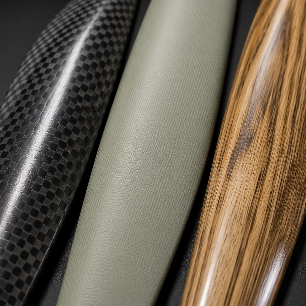
Propeller material determines the blade's stiffness-to-weight ratio, fatigue life, damage tolerance and manufacturing consistency. The three material families in current industrial UAV use are carbon fiber reinforced polymer (CFRP), glass-fiber-reinforced nylon (injection-molded), and wood-composite (laminated hardwood with epoxy or polyurethane coating). Each has a distinct performance envelope and procurement profile.
Carbon fiber (CFRP). The highest stiffness-to-weight ratio of the three families — typical tensile modulus of 70–120 GPa for standard-modulus carbon fiber in an epoxy matrix, compared to 8–15 GPa for glass-reinforced nylon and 12–18 GPa for laminated hardwood. This stiffness means the blade deflects less under aerodynamic load, maintaining its designed pitch angle across the span and producing thrust that closely matches the theoretical prediction. Carbon fiber propellers are manufactured by compression molding — layers of pre-impregnated carbon fiber fabric are laid into a mold, compressed under heat and pressure, and cured. The manufacturing process enables consistent blade geometry from part to part (aerodynamic profile deviation typically within ±0.1 mm at any span station), which translates into lower vibration and better balance consistency across a production lot. The trade-off is cost — a 15-inch carbon fiber propeller for industrial UAV use typically costs USD 18–45 per unit, 3–6 times the cost of an equivalent nylon propeller — and brittleness: carbon fiber has essentially zero plastic deformation before fracture, meaning a blade strike that a nylon propeller would survive with a chipped tip will shatter a carbon fiber propeller. For missions where a propeller strike is a realistic operational risk — agricultural spraying at low altitude over uneven terrain, delivery UAVs landing in unprepared zones — the higher replacement cost of carbon fiber must be factored into the operating cost per flight hour. Carbon fiber propellers are the standard choice for industrial inspection, mapping, survey and other missions where vibration control, efficiency and long service life (500–1,000 flight hours between replacements under normal operation) justify the higher unit cost.
 Concept illustration
Glass-reinforced nylon (injection-molded). The lowest cost option — USD 4–12 per unit for a 15-inch propeller — with adequate performance for applications where the efficiency penalty (typically 5–15% lower grams-per-watt compared to carbon fiber at the same diameter and pitch, due to blade deflection under load reducing the effective pitch) is acceptable in exchange for lower unit cost and higher impact resistance. Nylon propellers are manufactured by injection molding, a process with high throughput but less dimensional consistency than compression-molded carbon fiber — blade-to-blade mass variation within a production lot can be ±3% for nylon compared to ±0.5% for carbon fiber, requiring post-molding balancing (typically by clipping small amounts of material from the heavier blade tip) to achieve an acceptable balance grade. Nylon propellers are also susceptible to UV degradation — the polymer chains break down under prolonged sunlight exposure, reducing tensile strength by 30–50% after 500–1,000 hours of outdoor exposure depending on the UV stabilizer package in the resin formulation. For UAVs that operate predominantly outdoors in high-UV environments (agricultural spraying in tropical latitudes, desert survey operations), nylon propellers should be replaced on a calendar-interval basis (every 6–12 months of outdoor storage and operation) regardless of flight hours, and the procurement team should specify UV-stabilized nylon grades (typically PA6 or PA66 with HALS — Hindered Amine Light Stabilizer — additive package) in the purchase specification. Nylon propellers are suitable for training and R&D UAVs, short-duration agricultural spraying operations, and delivery UAVs where propeller strike replacement cost is a significant operating expense.
Wood composite. A niche but viable option for large fixed-wing UAV propellers (18-inch diameter and above) where the combination of moderate stiffness, natural vibration damping and low cost is advantageous. Laminated hardwood propellers — typically maple or birch veneers bonded with epoxy and machined to an aerodynamic profile — have a natural internal damping characteristic that absorbs motor vibration more effectively than carbon fiber, reducing the vibration transmitted to the airframe and payload. This damping characteristic is particularly valuable for fixed-wing mapping UAVs where IMU vibration isolation is a critical performance parameter. The trade-off is moisture sensitivity — wood absorbs atmospheric moisture and swells, changing the blade geometry and balance. Wood composite propellers must be stored in humidity-controlled conditions (40–60% RH) and should be coated with a moisture-barrier finish (polyurethane or epoxy clear coat) renewed every 200–300 flight hours. Wood composite propellers cost USD 25–60 per unit at the 20-inch size, comparable to carbon fiber, and are typically sourced from specialized manufacturers rather than mass-production injection molding facilities.
Matching propeller to mission profile: a procurement methodology
The propeller selection process that produces a procurement-ready specification follows five steps, each building on the constraints established in the previous step. The methodology assumes the motor KV, battery voltage and ESC current rating have already been determined — the powertrain matching process covered in the powertrain matching article — and focuses on the propeller-specific decisions.
Step 1: Define the mission airspeed envelope. Record the minimum, typical and maximum airspeeds the UAV will operate at during its primary mission. A power line inspection UAV might operate at 0 m/s (hover at each tower), 8 m/s (transit between towers) and 15 m/s (return to launch). A mapping UAV might operate at 14 m/s (survey grid lines), 18 m/s (transit between grid blocks) and 22 m/s (return to launch). These airspeed numbers determine the pitch requirement — if the maximum airspeed exceeds 20 m/s, a pitch-to-diameter ratio below 0.45:1 will limit the top speed because the propeller cannot produce net thrust when the forward airspeed approaches the pitch speed (the RPM × pitch product, converted to m/s).
Step 2: Calculate the thrust-per-motor requirement. For a multirotor, the thrust-per-motor at hover is (all-up weight × 1.15) divided by the number of motors, where the 1.15 factor accounts for the thrust margin needed for control authority — the flight controller must be able to differentially vary motor thrust to maintain attitude, and if every motor is already at 100% of its hover thrust, there is no control margin. For a 12 kg octocopter, the hover thrust per motor is (12 × 9.81 × 1.15) / 8 = 16.9 N per motor. This thrust number, combined with the motor KV and battery voltage, determines the minimum propeller diameter — the propeller must produce the required thrust at a throttle percentage below 65% (to leave headroom for altitude hold, gust recovery and battery voltage sag at the end of the flight).
Step 3: Select the diameter based on the motor thrust table. Every motor manufacturer publishes a thrust table — RPM, current draw, thrust and efficiency (g/W) for a range of propeller sizes at a given voltage. Select the smallest diameter propeller that meets the thrust requirement at 60–65% throttle with the current draw below 80% of the ESC continuous rating. If no propeller in the manufacturer's table meets both criteria, the motor is undersized for the airframe — increase the motor stator volume or decrease the all-up weight target. Do not compensate by selecting a larger propeller that exceeds the motor's current rating at full throttle; the current spike during a rapid climb will trigger ESC over-current protection and the UAV will lose altitude at the moment it most needs thrust.
Step 4: Adjust pitch for the mission airspeed profile. Start with the pitch recommended in the mission-type table above (section 2), then refine based on flight test data. The refinement methodology: fly the UAV in its primary mission profile, log the motor RPM and current draw, and plot the operating point on the motor manufacturer's efficiency map. If the operating point falls in the 70–85% efficiency band, the pitch is correct. If it falls below 70% — typically because the propeller is operating at a high angle of attack where the blade is partially stalled — reduce the pitch by 0.5–1 inch and re-test. If it falls above 85% — rare but possible with a very conservative pitch selection — the pitch can be increased to extract more thrust per watt, with the caveat that increasing pitch moves the stall angle of attack to a lower airspeed, which may reduce efficiency in the hover portion of the mission.
Step 5: Specify blade count, material and procurement requirements. Choose two blades for maximum efficiency, three blades if the diameter constraint or acoustic requirement demands it. Choose carbon fiber for missions prioritizing vibration control, efficiency and service life; nylon for missions prioritizing unit cost and impact resistance; wood composite for large fixed-wing applications. Specify the balance grade (G6.3 minimum, G2.5 for precision applications), the diameter tolerance (±0.5% of nominal), and the UV stabilizer requirement (for nylon propellers deployed outdoors). Request a first-article inspection report from the manufacturer for each production lot, including measured diameter, pitch at the 75% radius station, mass per blade, and the balance grade certification. The UAV supplier evaluation checklist provides the audit framework for qualifying propeller manufacturers, which applies the same supplier qualification rigor as for flight controllers and ESCs.
Propeller efficiency metrics for procurement and acceptance testing
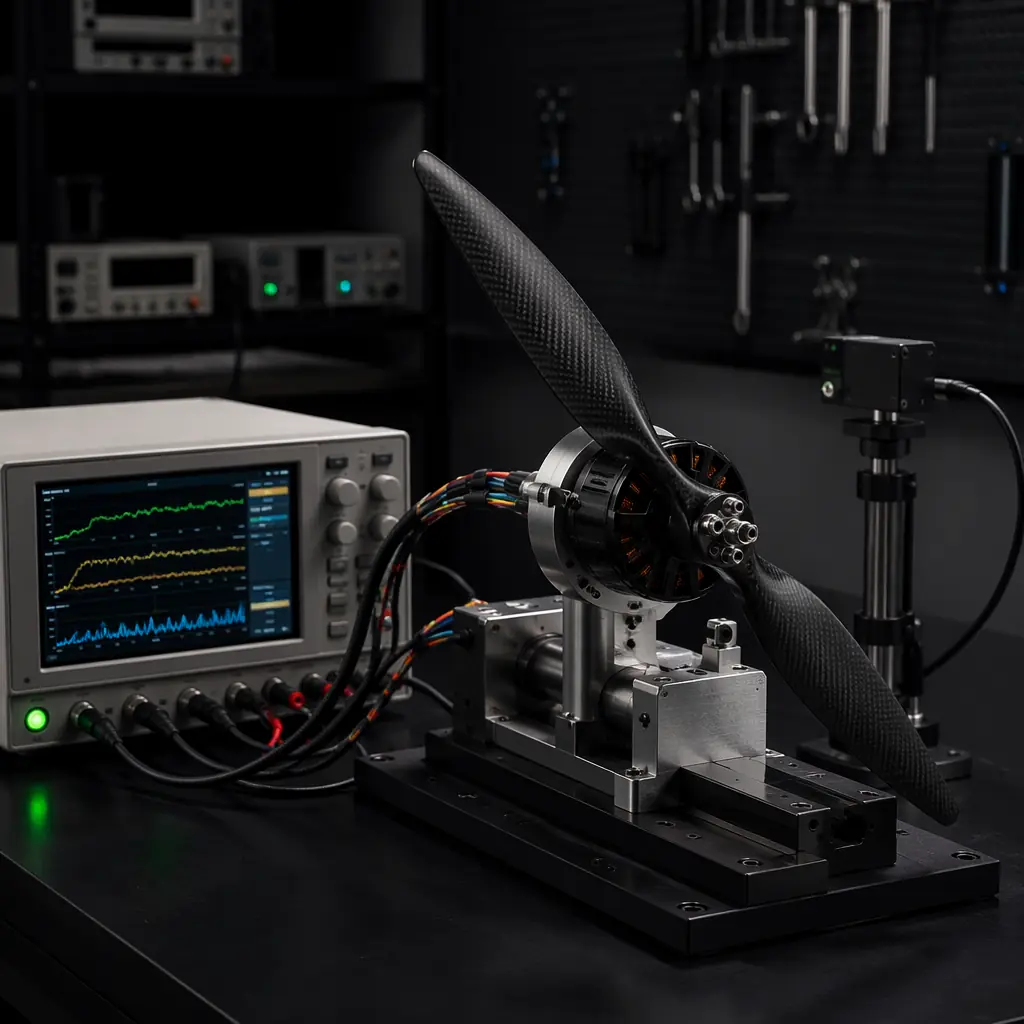
Three efficiency metrics should be specified in the propeller procurement document and verified during incoming inspection. These metrics are measured on a static thrust stand — a calibrated load cell measuring thrust, an optical or magnetic RPM sensor, and a power analyzer measuring DC voltage and current at the ESC input — and should be recorded at the battery's nominal voltage (e.g., 22.2 V for 6S) with the propeller mounted on the production motor (not a reference motor, because the motor's own efficiency curve affects the system-level measurement).
Static thrust efficiency (g/W). Measured at 50% throttle, 75% throttle and 100% throttle. The procurement specification should state the minimum acceptable g/W at the mission cruise throttle (typically 65–75% for multirotors). For a 15-inch carbon fiber propeller on a well-matched motor, the expected static thrust efficiency at 75% throttle is 7.5–9.5 g/W at sea level. Values below 6.0 g/W indicate a pitch mismatch, a motor efficiency problem or a propeller manufacturing defect (incorrect pitch angle, surface roughness from poor mold finish). This metric should not be confused with the propeller's aerodynamic efficiency — the g/W number includes the motor's efficiency, the ESC's efficiency and the propeller's aerodynamic efficiency as a system, which is the measurement that matters for flight time prediction.
Thrust consistency across a production lot. Measure the static thrust at 75% throttle for 10 randomly selected propellers from a production lot. The coefficient of variation (standard deviation divided by mean) should be below 2% for carbon fiber and below 5% for nylon. A CV above these thresholds indicates inconsistent manufacturing — mold wear in injection molding, inconsistent layup compression in carbon fiber molding, or material batch variation — that will produce blade-to-blade imbalance when propellers from different positions in the production lot are mounted on different motors in the same UAV. The worst-case scenario is a quadcopter where two motors have propellers from the high-thrust end of the production distribution and two have propellers from the low-thrust end: the flight controller compensates by running the low-thrust motors at higher RPM, which increases their current draw and reduces their flight-time contribution, and the net effect is a 5–10% reduction in total flight time compared to a perfectly matched set.
Noise level at mission cruise RPM. Measured with a sound level meter at 1 meter distance, A-weighted. While not a direct efficiency metric, noise level is correlated with aerodynamic efficiency — a propeller that produces excessive noise at cruise RPM typically has turbulent flow separation at the blade tip or trailing edge, which dissipates energy that should be converted to thrust. The procurement specification should state a maximum acceptable sound pressure level at the mission cruise RPM, typically 68–75 dBA at 1 meter for a 15-inch propeller operating at 5,000–6,000 RPM. Values above 80 dBA suggest a blade design or manufacturing problem that should be investigated before accepting the production lot.
 Concept illustration
Common propeller selection mistakes and how procurement teams catch them
Five recurring propeller selection errors appear in UAV integration projects, and a procurement team that knows these patterns can catch them during the component specification review — before the first flight test reveals the problem.
Mistake 1: Selecting propeller by "looks right" rather than by thrust table. A 15-inch propeller from Manufacturer A is not aerodynamically equivalent to a 15-inch propeller from Manufacturer B — the blade planform (the chord distribution along the span), the airfoil section (the cross-sectional shape at each span station), and the pitch distribution (whether the pitch is constant along the span or varies — most modern propellers use a variable pitch distribution that is higher at the root and lower at the tip to optimize the local angle of attack) all differ between manufacturers. Two propellers with the same nominal diameter and pitch can differ in static thrust by 10–20% and in current draw by 15–25%. The procurement specification must reference a specific manufacturer part number and a specific thrust table. "15×5.5 carbon fiber propeller" is not a procurement specification. "T-Motor CF1555, thrust per manufacturer table T-CF1555-6S dated 2025-03, minimum 2,150 g at 50% throttle at 22.2 V" is a procurement specification.
Mistake 2: Ignoring the altitude correction. A propeller selected and tested at sea level will produce 10–15% less thrust at 2,000 m altitude and 20–30% less at 3,500 m. A UAV designed for agricultural spraying in the Colombian Andes (operating altitude 2,500–3,200 m) that uses a propeller selected from a manufacturer's sea-level thrust table will be significantly under-thrusted — the motors will run at higher throttle to compensate, drawing more current, reducing flight time and potentially exceeding the ESC thermal limit. The procurement specification must state the maximum operating altitude and require either altitude-corrected thrust data from the manufacturer or a commitment to perform acceptance testing at the specified altitude. For operations above 3,000 m, the airframe materials guide covers the structural implications of reduced air density on propeller and motor mounting — the same thrust margin issue applies to the structural load path.
Mistake 3: Specifying a single blade count without evaluating the efficiency trade-off. Locking the propeller specification to "3-blade only" without quantifying the acceptable efficiency penalty can eliminate supply options that would meet the mission requirement at lower cost or shorter lead time. The procurement specification should express the blade count as a range — "2-blade or 3-blade acceptable, 3-blade preferred if efficiency at mission cruise RPM is within 8% of the 2-blade baseline" — which allows the supply chain to offer alternatives without compromising the mission performance threshold.
Mistake 4: Neglecting the propeller as a lifecycle cost item. The procurement budget that allocates USD 800 for four carbon fiber propellers on a quadcopter but does not budget for the 4–8 replacement sets over the platform's 2,000-hour design life has underestimated the propeller total cost of ownership by a factor of 5–9. The propeller procurement plan should include the estimated replacement interval (based on the material, operating environment and mission profile), the unit cost at the procurement volume, and the lead time for replacement orders — sourcing from a manufacturer with 12-week lead time for small-quantity reorders creates a platform availability risk when propellers are damaged in the field and the operator cannot wait 12 weeks for replacements. The build vs. buy framework covers the lifecycle cost modeling methodology that applies equally to propellers and all other UAV components.
Mistake 5: Not testing the propeller with the production BMS firmware. The battery management system's discharge current limit interacts with the propeller's current draw profile. A BMS configured with a conservative discharge current limit — set to protect the battery cells from over-current damage — may trigger a current-limiting event during a rapid climb when the propeller demands current above the BMS threshold, causing a sudden reduction in available power at the moment the UAV most needs it. The propeller acceptance test must be performed with the production BMS firmware and the production battery pack, not with a laboratory power supply that has no current limiting. The interaction between the propeller's current draw and the battery's discharge characteristic is covered in the UAV battery and power management guide, which provides the cell-level discharge curves that should be referenced during propeller testing.
Explore custom engineering Back to Blog
Continue Reading
UAV Powertrain Matching
Voltage, protocol, KV rating and propeller load — how to match the full propulsion chain for industrial UAVs.
ESC Firmware Selection Guide
BLHeli_32 vs AM32 vs FOC — how ESC firmware choice affects throttle response for the propeller load.
UAV Battery & Power Management
LiPo vs Li-Ion discharge curves, BMS current limiting and how battery sag interacts with propeller current draw.
UAV Airframe Materials Guide
How propeller-induced vibration propagates through carbon fiber vs aluminum vs G10 airframe structures.
Supplier Evaluation Checklist
The 10-point audit framework for qualifying propeller manufacturers and other UAV component suppliers.