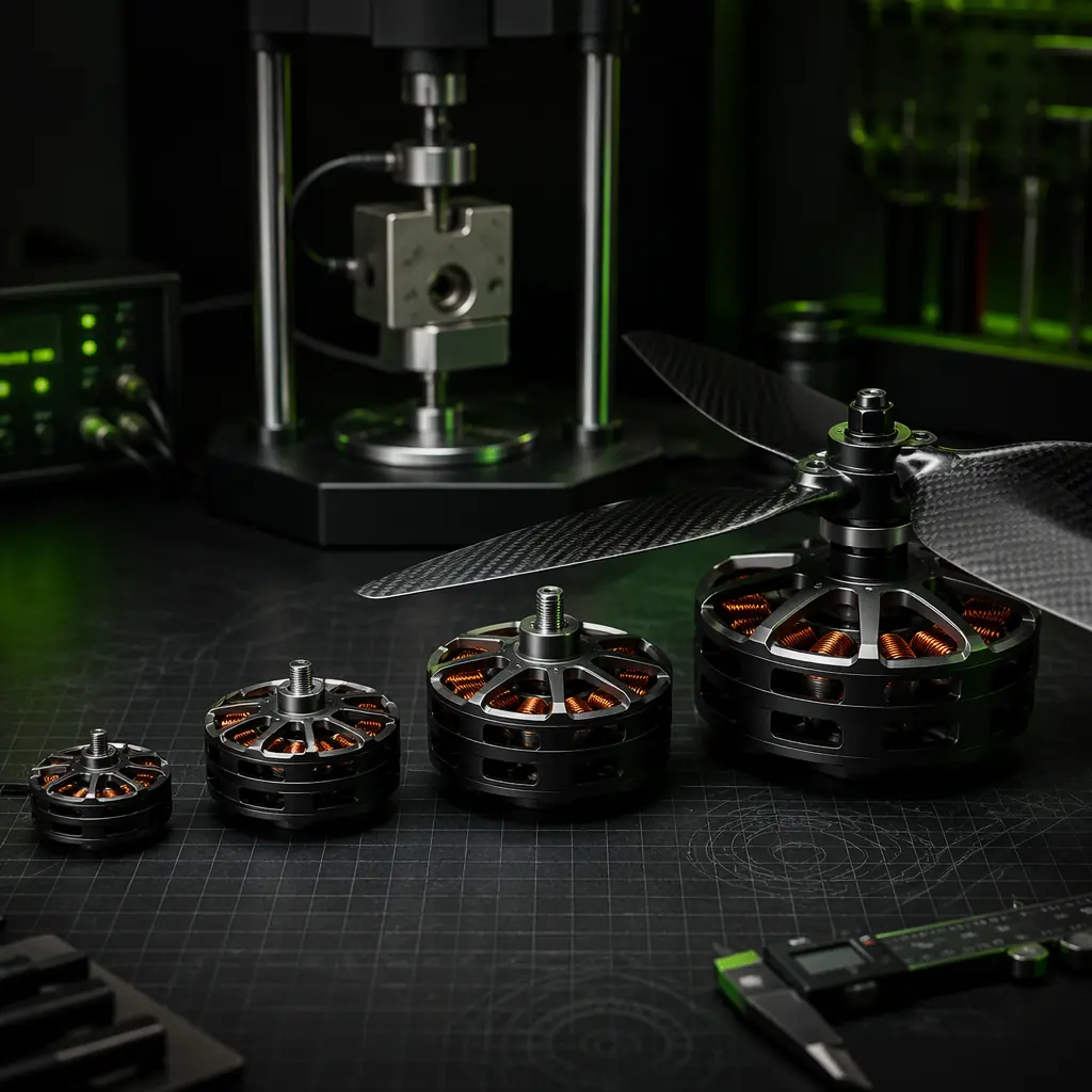
The KV specification originated in the radio-controlled model aircraft hobby, where a "2,400 KV motor on 3S" was shorthand for a high-RPM power system suitable for a small park-flyer. That shorthand has become institutionalized in the industrial UAV supply chain, but it no longer serves procurement teams who need to specify motors for 10–25 kg multirotors operating at 6S–14S voltages with mission durations of 45–90 minutes. A 400 KV motor from Manufacturer A may have a stator volume of 12.6 cm³ (a 41 mm diameter × 14 mm stack length stator, typically rated for 800–1,200 watts continuous) while a 400 KV motor from Manufacturer B may have a stator volume of 25.1 cm³ (a 52 mm × 15 mm stator, typically rated for 1,800–2,500 watts) — both are "400 KV," both are "for 6S–12S," but the second motor can sustain nearly three times the continuous power of the first because KV does not encode the motor's torque capacity, only its speed constant. Selecting a motor by KV alone is like selecting an engine by its redline RPM alone — it tells you the maximum speed but nothing about the torque, the power band or the thermal limit.
This article builds a motor selection methodology from the procurement team's perspective. It starts with the physical definition of KV — the back-EMF constant and its relationship to winding turns, stator slot count and magnet pole count — and progresses through the thrust calculation that connects KV, battery voltage, propeller geometry and motor current to the UAV's takeoff weight. It covers stator sizing: the relationship between stator volume and continuous power, and how to read a motor manufacturer's datasheet to distinguish a motor that can sustain 800 watts for 60 minutes from one that can sustain 800 watts for 30 seconds. It addresses thermal limits — the winding temperature rise under sustained load, the magnet demagnetization threshold and the bearing life derating curve — which are the three constraints that determine whether a motor selected on paper will survive a 90-minute mapping mission. And it provides a procurement checklist that the team can use to verify a motor's specifications against the mission requirements before committing to a purchase order. For the broader propulsion system integration — matching the motor to the ESC and the flight controller, and the end-to-end powertrain validation procedure — the UAV powertrain matching guide covers the system-level integration. For the propeller selection methodology that determines the load on the motor, the UAV propeller selection guide covers the diameter, pitch and material decisions that drive the torque demand. This article focuses on the motor — the rotating machine that converts electrical power into thrust.
KV from first principles: what the number on the datasheet actually means
KV is the motor's velocity constant: the RPM the motor will spin at per volt of applied voltage when unloaded — no propeller, no mechanical load, just the motor spinning freely. The physical origin of KV is Faraday's law of induction: when a permanent magnet rotor spins past a stator winding, the changing magnetic flux through the winding induces a voltage — the back-EMF — that opposes the applied voltage. At the no-load speed, the back-EMF equals the applied voltage, and no current flows (ignoring the small current required to overcome bearing friction, windage and iron losses). The ratio of the back-EMF to the rotational speed is the motor's electrical constant, expressed in volts per radian per second — the inverse of KV. A 100 KV motor produces 1 volt of back-EMF at 100 RPM, or equivalently 0.01 volts per RPM. A 400 KV motor produces 1 volt at 400 RPM, or 0.0025 volts per RPM.
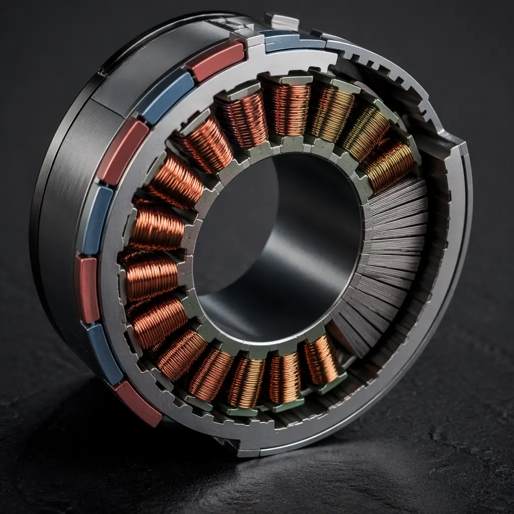
The winding configuration determines KV. A motor with more turns of wire per stator tooth produces a higher back-EMF for the same speed — and therefore a lower KV. A motor wound with 10 turns of 0.4 mm diameter wire on each stator tooth might produce a KV of 400; the same motor wound with 20 turns of 0.28 mm diameter wire (half the cross-sectional area, to fit the same slot space) would produce a KV of approximately 200 — half the speed constant, because the back-EMF is proportional to the number of turns. The trade-off is that the lower-KV winding uses thinner wire, which has higher resistance — the 20-turn winding has approximately 4 times the phase resistance of the 10-turn winding (twice the length from twice the turns, and half the cross-sectional area from the thinner wire, giving R ∝ turns²). Higher resistance means higher I²R losses for the same current — the 200 KV motor will run hotter than the 400 KV motor at the same torque output. This is the fundamental motor design trade-off: lower KV reduces the RPM for a given battery voltage (allowing a larger, more efficient propeller) but increases the winding resistance (reducing efficiency at high torque). The procurement team's job is to find the KV that balances propeller efficiency against motor efficiency for the specific mission — and that balance point is different for a 15 kg logistics UAV hovering at 50% throttle for 45 minutes than for a 3 kg inspection UAV accelerating and decelerating repeatedly during a 25-minute power line patrol.
 Concept illustration
KV, battery voltage and the RPM target: the first constraint
The motor's operating RPM under load is approximately KV × voltage × throttle percentage, minus a speed droop of 5–15% due to winding resistance and ESC losses. For a UAV in hover — the condition that determines the motor's continuous power rating — the throttle percentage is typically 45–55% for a well-matched propulsion system (sufficient margin for climb and maneuvering without operating the motor in an inefficient region of its efficiency curve). The RPM at hover, multiplied by the propeller's pitch speed (the theoretical forward speed at which the propeller's angle of attack drops to zero, equal to RPM × pitch / 60 in meters per second for pitch in meters), determines the hover efficiency — and the hover efficiency, measured in grams of thrust per watt of electrical power (g/W), is the single most important performance metric for a multirotor UAV.
The procurement team's first calculation is therefore: what RPM does the propeller need to turn at to produce the required thrust, and what battery voltage × KV combination produces that RPM at 50% throttle? For a typical industrial multirotor with a 15–18 inch propeller (381–457 mm diameter) and a 5–6 inch pitch (127–152 mm), hover RPM is typically 4,500–6,500 RPM for a 4–8 kg thrust-per-motor configuration. A 6S battery (22.2 V nominal) with a 400 KV motor produces 22.2 × 400 = 8,880 RPM unloaded — at 50% throttle, approximately 4,000–4,400 RPM after droop. That is slightly below the target hover RPM for a 15-inch propeller, which means the motor will operate at 55–65% throttle in hover — acceptable but with reduced margin for climb. A 450 KV motor on 6S produces 22.2 × 450 = 9,990 RPM unloaded, approximately 4,500–5,000 RPM at 50% throttle — a better match for the 15-inch propeller. Alternatively, a 400 KV motor on 8S (29.6 V nominal) produces 29.6 × 400 = 11,840 RPM unloaded, approximately 5,300–5,900 RPM at 50% throttle — suited for a 14-inch propeller at higher disk loading or a 16-inch propeller with a steeper pitch. The KV selection is not independent of the battery voltage selection — they are two sides of the same RPM target equation — and the procurement team must specify both together, not one and then the other.
The relationship between battery voltage, KV and system efficiency is covered in detail in the UAV battery and power management guide, which addresses the discharge characteristics of LiPo and Li-Ion packs under sustained UAV loads and the voltage sag that reduces the effective RPM by 5–10% below the nominal-voltage calculation during the latter half of the flight. The propeller selection methodology — which determines the torque demand that the motor must meet at the target RPM — is covered in the UAV propeller selection guide, which provides the thrust coefficient, power coefficient and efficiency curves for common industrial UAV propellers.
Stator volume: the hidden specification that determines continuous power
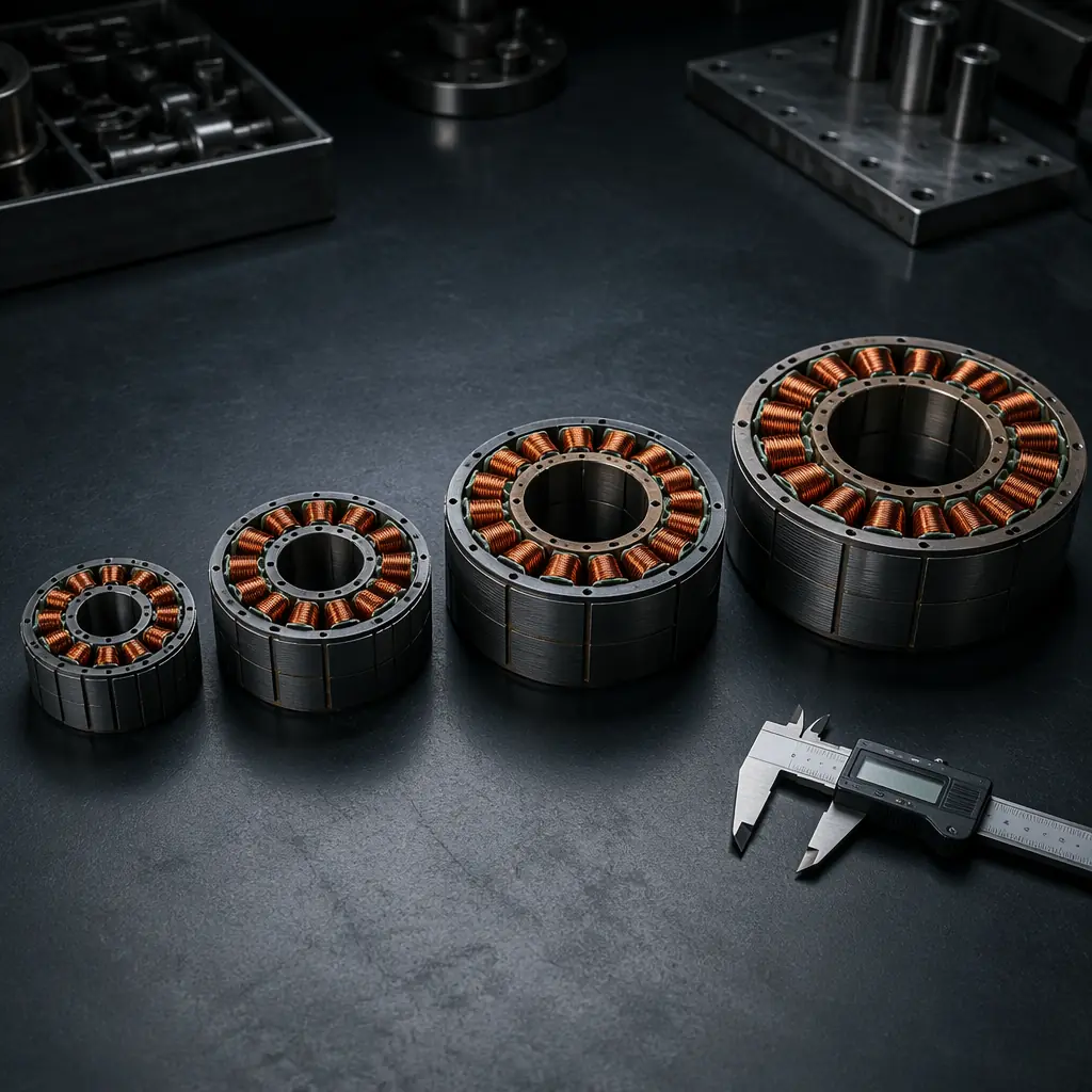
If KV is the motor's speed constant, stator volume is its torque capacity — and torque capacity, not RPM, determines how much power the motor can sustain without overheating. The stator is the stationary iron core with copper windings that produces the rotating magnetic field; its volume — approximately the stator diameter squared multiplied by the stator stack length — determines the magnetic flux that the motor can generate and the heat that it can dissipate. For a given stator volume, the motor's continuous torque is approximately constant regardless of the KV winding — a 400 KV and a 200 KV winding on the same stator will produce approximately the same continuous torque (because the lower-KV winding has higher resistance, which cancels the torque-per-amp advantage of the higher turn count), but the 400 KV winding will produce that torque at twice the RPM (and therefore twice the power) for the same battery voltage. The practical implication: a motor with a 41 mm × 14 mm stator (volume approximately 18.5 cm³) can sustain approximately 800–1,200 watts continuous, regardless of whether it is wound for 400 KV, 500 KV or 600 KV — the KV changes the RPM at which that power is delivered, not the power itself.
The procurement team should read the motor datasheet with stator volume as the primary differentiator, not KV. A motor manufacturer's product line typically spans a range of stator sizes, each offered in multiple KV windings. The 35 mm stator series (35 mm diameter × 10–12 mm stack, volume approximately 10–12 cm³) is typically rated for 400–600 watts continuous and is suitable for 3–5 kg UAVs with 12–14 inch propellers on 4S–6S. The 41 mm stator series (41 mm × 14 mm, approximately 18.5 cm³) is typically rated for 800–1,200 watts and is suitable for 6–12 kg UAVs with 15–17 inch propellers on 6S–8S. The 52 mm stator series (52 mm × 15–18 mm, approximately 32–38 cm³) is typically rated for 1,800–3,000 watts and is suitable for 12–25 kg UAVs with 18–22 inch propellers on 8S–12S. The 62 mm stator series (62 mm × 20–24 mm, approximately 60–75 cm³) is typically rated for 3,500–6,000 watts and is suitable for 25–50 kg UAVs with 22–30 inch propellers on 12S–14S. These are approximate ranges — the exact continuous power rating depends on the motor's cooling (open-frame motors with exposed windings dissipate heat more effectively than enclosed motors with a sealed rotor bell), the ambient temperature (a motor rated for 1,200 watts at 25°C ambient may be derated to 900 watts at 45°C ambient, which is the typical temperature inside a UAV's motor bay on a summer day in the Middle East or Southeast Asia) and the flight profile (a motor that alternates between hover and climb dissipates heat less effectively than a motor in steady-state cruise, because the climb phases push the winding temperature above the steady-state value and the hover phases do not provide enough cooling time to bring it back down).
 Concept illustration
Thrust calculation: from KV and propeller to takeoff weight
The procurement team's motor selection must start with a thrust target, not a KV target. The thrust target is determined by the UAV's all-up weight (AUW) — the weight of the airframe, propulsion, avionics, battery, payload and any ancillary equipment, in kilograms — multiplied by the thrust-to-weight ratio (TWR) required for the mission profile. A multirotor UAV in hover requires a total thrust equal to its weight, distributed across N motors: thrust per motor = AUW × 9.81 / N, in newtons. For a 12 kg hexacopter (6 motors) in hover, the thrust per motor is 12 × 9.81 / 6 = 19.6 N per motor, or approximately 2.0 kgf per motor. The TWR at maximum throttle — the thrust available for climb and maneuvering — should be at least 1.8:1 for a multirotor operating in calm conditions (adequate for gentle climbs and moderate wind compensation) and 2.2:1 to 2.5:1 for a multirotor operating in gusty conditions, at high altitude (where reduced air density reduces propeller thrust by 10–15% per 1,000 meters of density altitude above sea level, approximately) or with a safety-critical payload that must be recovered even if one motor fails (the hexacopter with one motor out loses approximately 15–20% of total thrust, so the remaining five motors must provide at least 12 × 9.81 = 117.7 N, or 23.5 N per motor — a 20% increase over the hover thrust).
With the thrust target defined, the procurement team works backward to the motor specification. The propeller manufacturer's thrust data — typically provided as a table or curve of thrust (N) vs RPM for a given propeller diameter, pitch and air density — gives the RPM required to produce the target thrust. For a 15 × 5.5 inch carbon fiber propeller (381 mm diameter, 140 mm pitch) producing 20 N of thrust at sea level in static conditions (ISA standard atmosphere, 15°C, 1013.25 hPa), the required RPM is approximately 5,800–6,200 — depending on the propeller brand and the specific airfoil design, which the procurement team should verify with the propeller manufacturer's published thrust data rather than relying on generic estimates. The motor's KV × battery voltage product must produce an unloaded RPM of approximately 6,200 / 0.50 = 12,400 RPM (assuming 50% throttle for hover), which at 6S nominal (22.2 V) requires a KV of 12,400 / 22.2 = 559 — approximately 550–600 KV. Alternatively, at 8S nominal (29.6 V), the required KV is 12,400 / 29.6 = 419 — approximately 400–450 KV. Both combinations meet the thrust target; the choice between them is determined by the motor's efficiency at the operating point (higher voltage + lower KV generally improves efficiency by reducing I²R losses, at the cost of a heavier battery for the same watt-hour capacity because 8S packs have more cells in series and therefore more cell packaging weight per watt-hour) and by the ESC's voltage rating (a 6S ESC is smaller, lighter and cheaper than an 8S ESC for the same current rating, but an 8S system operates at lower current for the same power and therefore generates less heat in the ESC MOSFETs and the power wiring).
The procurement team should also calculate the motor's power consumption at the target thrust. The propeller manufacturer's thrust data typically includes power (watts) vs RPM — at 6,000 RPM, a 15 × 5.5 inch propeller typically absorbs 400–550 watts, depending on the propeller's efficiency (a high-efficiency carbon fiber propeller with a thin, optimized airfoil may absorb 420 watts at 20 N thrust, for an efficiency of 20 / 420 = 0.048 N/W, or 4.9 g/W; a lower-efficiency nylon propeller may absorb 520 watts for the same 20 N, for 3.9 g/W — a 25% difference in flight time for the same battery capacity). The motor's electrical input power is the propeller's absorbed power divided by the motor's efficiency at the operating point — typically 80–88% for a well-designed brushless motor at its optimal current — so the motor's electrical input power is approximately 420 / 0.85 = 494 watts. At 6S (22.2 V nominal), the motor current is 494 / 22.2 = 22.3 A per motor — and for a hexacopter, the total current draw in hover is 6 × 22.3 = 133.8 A, which determines the battery capacity required for the target flight time (a 22,000 mAh 6S pack at 133.8 A will discharge to 20% remaining capacity — the safe minimum for LiPo packs — in approximately 22,000 × 0.8 / 133,800 × 60 = 7.9 minutes of hover; for a 45-minute mission, the hover current must be reduced to 22,000 × 0.8 / 45 × 60 = 23.5 A total, or 3.9 A per motor, which requires a larger propeller turning at lower RPM to produce the same 20 N of thrust at lower power — a classic motor-propeller matching optimization problem).
Thermal limits: winding temperature, magnet demagnetization and bearing life
The motor's power rating on the datasheet is a thermal rating, not a mechanical rating. The motor can mechanically withstand far more power than it can thermally sustain — the copper windings, the neodymium magnets and the bearings are the three thermal weak links, and each imposes a different constraint on the motor's continuous power.
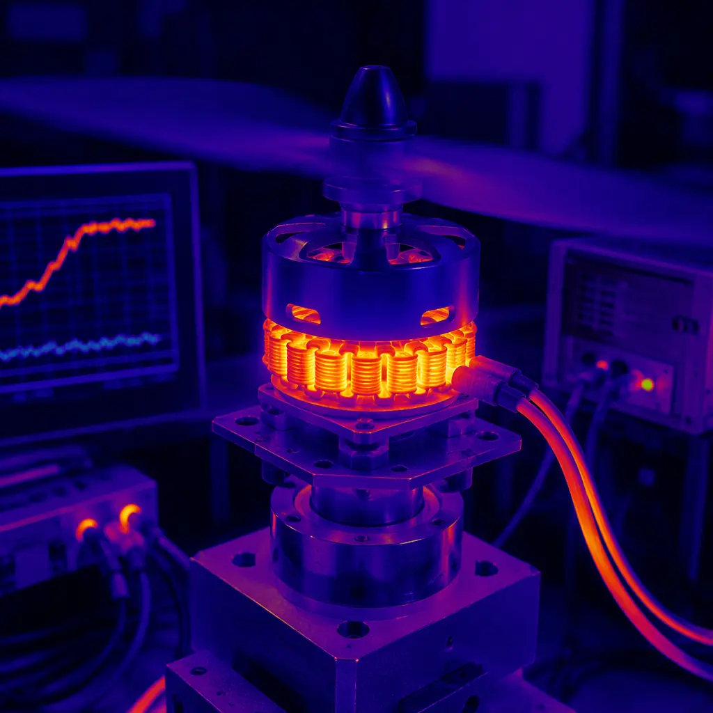
Winding temperature. The copper windings are insulated with a polymer enamel coating — typically polyurethane, polyester or polyimide, with temperature ratings of 130°C (Class B), 155°C (Class F), 180°C (Class H) or 220°C (Class C). When the winding temperature exceeds the insulation's rating, the enamel degrades — it becomes brittle, cracks, and eventually creates a short circuit between adjacent turns in the same coil. A shorted turn reduces the motor's KV (because the effective number of turns decreases), increases the current draw (because the shorted turn acts as a short-circuited secondary winding in a transformer) and generates additional heat in the short — a positive feedback loop that can destroy the motor within seconds of the first short. The procurement specification should require that the motor's continuous power rating be validated with a winding temperature measurement (thermocouple embedded in the winding, not on the stator surface, because the winding temperature can be 20–40°C higher than the stator surface temperature) at the specified ambient temperature and at the maximum continuous power for the mission duration — not just for a 30-second bench test. The winding temperature must remain at least 20°C below the insulation class rating at the end of the mission (so a Class F motor — 155°C rating — must have a winding temperature below 135°C after 60 minutes at maximum continuous power at the specified ambient temperature).
Magnet demagnetization. Neodymium magnets — the standard for UAV brushless motors — have a maximum operating temperature of 80°C (N-grade), 100°C (M-grade), 120°C (H-grade), 150°C (SH-grade), 180°C (UH-grade) or 200°C (EH-grade), above which they begin to lose magnetization irreversibly. Most UAV motors use N-grade or M-grade magnets (80–100°C maximum), which is adequate for a motor whose winding temperature stays below 135°C and whose rotor (where the magnets are mounted, on the inside of the rotor bell) is cooled by the airflow from the propeller — but if the motor is enclosed or the airflow is restricted (as in a sealed motor pod on a fixed-wing UAV), the rotor temperature can approach the winding temperature, and the magnets can demagnetize even though the windings are within their insulation rating. The procurement specification should require the magnet grade and the maximum rotor temperature at the maximum continuous power — verified by a thermocouple on the rotor bell or by an infrared pyrometer aimed at the rotor through a ventilation port. For UAVs operating in high ambient temperatures (desert operations, engine compartment mounting on a hybrid VTOL), M-grade or H-grade magnets (100–120°C) are recommended, at a cost premium of approximately 10–20% over N-grade.
Bearing life. The motor bearings — typically 6000-series or 6200-series deep-groove ball bearings in sizes from 4 × 10 × 4 mm (for 22–28 mm stators) to 10 × 19 × 5 mm (for 52–62 mm stators) — have a rated life (L10, the life at which 10% of bearings in a population will have failed) that is inversely proportional to the cube of the load and exponentially dependent on temperature. A bearing operating at 80°C has approximately half the L10 life of the same bearing operating at 60°C, assuming the same load and the same lubrication. The procurement specification should require the bearing type (shielded or sealed — sealed bearings retain lubrication but have higher friction; shielded bearings have lower friction but lose lubrication over time), the bearing size (a larger bearing distributes the radial load from the propeller — which is the dominant bearing load in a multirotor, caused by the propeller's gyroscopic precession during pitch and roll maneuvers — over a larger contact area, reducing the contact stress and extending life), and the bearing's speed rating (the bearing must be rated for the motor's maximum RPM, which can exceed 12,000 RPM for a 600 KV motor on 6S).
 Concept illustration
For the ESC selection that drives the motor — and particularly the ESC's current rating, which must accommodate the motor's peak current during climb, and the ESC's thermal management, which must dissipate the heat generated by the MOSFET switching losses at the motor's PWM frequency — the ESC firmware selection guide covers the BLHeli_32, AM32 and FOC firmware options and their respective thermal performance. For the system-level powertrain matching that ensures the motor, ESC, battery and propeller are compatible across the full flight envelope — not just at the hover operating point — the UAV powertrain matching guide provides the end-to-end validation methodology.
Motor KV procurement checklist
The following checklist is a procurement-ready summary of the motor specification items that must be verified before placing a purchase order. Each item includes the verification method and the acceptable range or value.
Stator specifications. Stator diameter (mm) and stack length (mm) — these determine the stator volume and therefore the continuous power capability. Verify with a dimensional drawing or a physical measurement of a sample motor. The stator lamination thickness — typically 0.20 mm or 0.35 mm — determines the iron losses at high RPM; 0.20 mm laminations reduce eddy current losses by approximately 40% compared to 0.35 mm at 10,000 RPM. The magnet pole count and stator slot count — typically 12N14P (12 stator slots, 14 magnet poles) or 24N28P for larger motors — determine the cogging torque and the electrical frequency at the operating RPM, which affects the ESC's commutation timing accuracy.
KV tolerance and measurement conditions. The manufacturer's KV specification should state the measurement method (no-load, at the motor's rated voltage, at room temperature) and the tolerance — typically ±5% for quality motors, ±10% for commodity motors. A 400 KV motor with a +10% tolerance is actually 440 KV — which produces 10% higher RPM at the same voltage, potentially pushing the propeller's tip speed into the transonic regime (Mach 0.7–0.8 at the tip, where drag increases sharply and efficiency collapses) and increasing the motor's no-load current by 15–25%. The procurement specification should require KV tolerance of ±5% or better. The phase resistance — measured at room temperature, typically 20–25°C, with a four-wire Kelvin measurement — determines the I²R losses and must be stated for each winding configuration. The no-load current at the rated voltage — the current the motor draws with no propeller, overcoming bearing friction, windage and iron losses — should be less than 5% of the motor's maximum continuous current for a quality motor; a no-load current above 10% indicates high iron losses (thick stator laminations, poor magnetic steel) or bearing drag (insufficient lubrication, contamination during assembly).
Continuous power and thermal validation. The continuous power rating must state the ambient temperature (typically 25°C), the test duration (minimum 30 minutes, preferably 60 minutes for an industrial UAV motor), the mounting configuration (the motor's heat dissipation depends on whether it is mounted to a carbon fiber arm — which is a thermal insulator — or an aluminum arm — which acts as a heatsink) and the airflow condition (the propeller's own downwash provides significant cooling — a motor tested on a bench without propeller airflow will reach a higher winding temperature than the same motor in flight, and the procurement team should account for this difference when comparing datasheet specifications). The winding temperature at the continuous power rating must be stated and must be at least 20°C below the insulation class rating. The magnet grade and maximum operating temperature must be stated — N, M, H, SH, UH or EH. The bearing size, type (shielded or sealed) and speed rating must be stated.
Mechanical specifications. The motor's weight (grams) — the single most important number for the propulsion system mass budget. The mounting pattern — the bolt circle diameter and the bolt size (typically M3 for 22–35 mm stators, M4 for 41–52 mm stators, M5 for 62 mm and larger) — must be compatible with the UAV's motor mounts. The shaft diameter — typically 4 mm for 22–28 mm stators, 5 mm for 35 mm stators, 6 mm for 41 mm stators, 8 mm for 52 mm stators, 10 mm for 62 mm stators — must be compatible with the propeller's hub bore. The propeller mounting method — collet adapter, bolt-on hub, or direct shaft — must be specified, and the procurement team should verify that the propeller manufacturer supplies a compatible hub or adapter for the motor's shaft. The motor's overall dimensions — diameter, height and shaft protrusion — must fit within the UAV's motor mounting envelope, with adequate clearance for the propeller (the propeller must not contact the airframe structure during normal operation or during a blade-strike event).
For the quality control and incoming inspection procedures that verify the motor's specifications against the datasheet before the motor is integrated into the UAV — including KV measurement, phase resistance measurement, insulation resistance testing and dynamic balance verification — the UAV supplier evaluation checklist provides the incoming inspection framework for propulsion components. For the broader propulsion system procurement strategy — including single-source vs dual-source motor qualification, lead-time management and the cost implications of motor customization (custom KV winding, custom shaft length, custom connector configuration) — the UAV component build vs buy guide covers the make-or-buy decision that determines whether the procurement team specifies an off-the-shelf motor or commissions a custom winding for the specific mission.
Explore custom engineering Back to Blog
Continue Reading
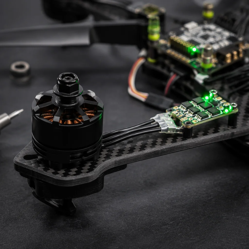
UAV Powertrain Matching
End-to-end propulsion system integration — matching the motor, ESC, battery and propeller across the full flight envelope, not just at hover.
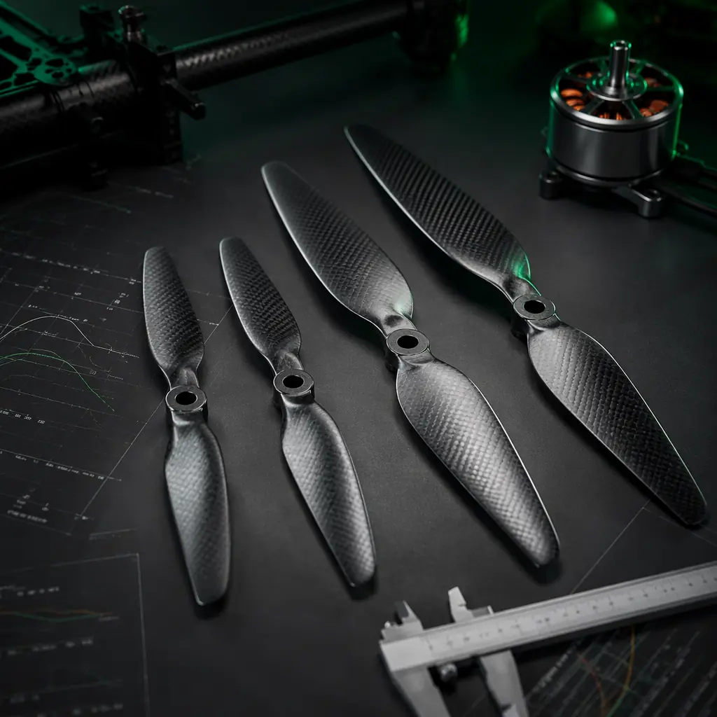
Propeller Selection Guide
Diameter, pitch, blade count and material decisions that determine the torque demand — the load that the motor's KV selection must satisfy.
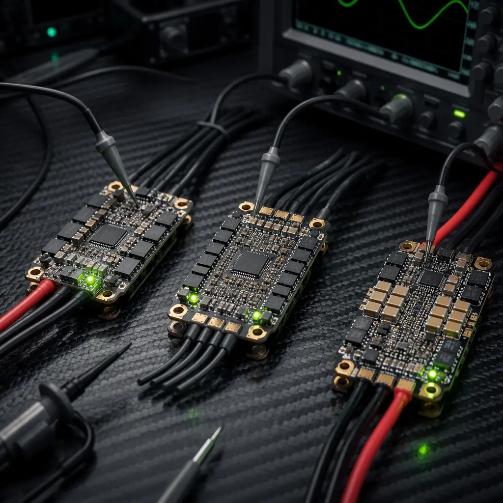
ESC Firmware Selection
BLHeli_32, AM32 and FOC — the ESC firmware that determines commutation timing, thermal performance and the motor's effective RPM control bandwidth.
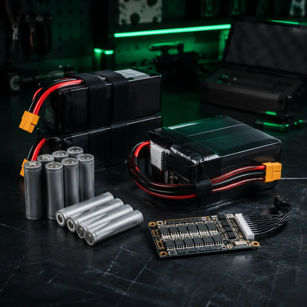
Battery & Power Management
Voltage sag under load — the 5–10% RPM reduction during flight that the motor's KV selection must account for in the thrust calculation.
UAV Airframe Materials Guide
Motor mount thermal conductivity — how the airframe material affects motor heat dissipation and continuous power rating.