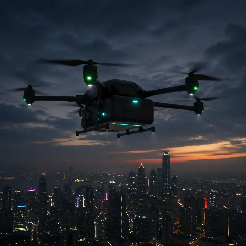
Drone delivery has moved from proof-of-concept demonstrations to operational deployments at scale. Zipline completed over 1 million commercial deliveries by early 2026. Wing passed 400,000 deliveries across three continents. The medical logistics segment alone — blood products, vaccines, diagnostic samples — is projected to reach USD 3.2 billion in annual component procurement by 2027. But the component supply chain for logistics UAVs is distinct from the general UAV market in one critical respect: a mapping drone that loses 10% of its endurance produces a dataset covering 90% of the planned area and the operator flies a second mission. A delivery drone that loses 10% of its endurance does not reach the destination. The procurement standard for logistics UAV components is not performance at nominal conditions — it is guaranteed performance at the worst-case combination of payload mass, headwind, temperature and route altitude that the mission profile specifies.
The logistics drone component chain has five interdependent links. The propulsion system determines whether the aircraft can lift the payload. The battery system determines how far it can carry it. The navigation system determines whether it can land within 1 meter of the delivery point. The communications system determines whether the operator can intervene if something goes wrong. And the payload release mechanism determines whether the cargo arrives intact. These five links are not independent — a heavier payload requires more thrust, which draws more current, which reduces battery endurance, which shrinks the mission radius. Procurement decisions made in isolation at each link produce a system that underperforms at every link. The integration methodology in the UAV powertrain matching guide provides the system-level framework; this article applies it to the specific requirements of cargo delivery missions.
Propulsion for heavy-lift: thrust-to-weight at mission mass
Delivery drones operate at thrust-to-weight ratios that are fundamentally different from inspection or mapping platforms. A mapping hexacopter carrying a 1.5 kg camera payload at 10 kg AUW (all-up weight) operates at approximately 2.2:1 thrust-to-weight — the motors produce roughly 22 kg of total thrust at hover throttle, providing 12 kg of excess thrust for climb and maneuver. A delivery hexacopter carrying a 5 kg cargo payload at 18 kg AUW needs the same 2.2:1 thrust-to-weight to maintain climb performance in a 5 m/s headwind, requiring approximately 40 kg of total thrust — nearly double the thrust output from a platform only 80% heavier.
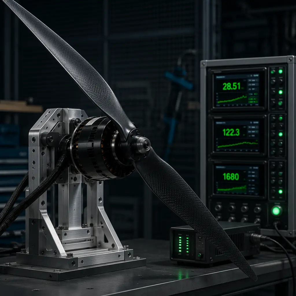
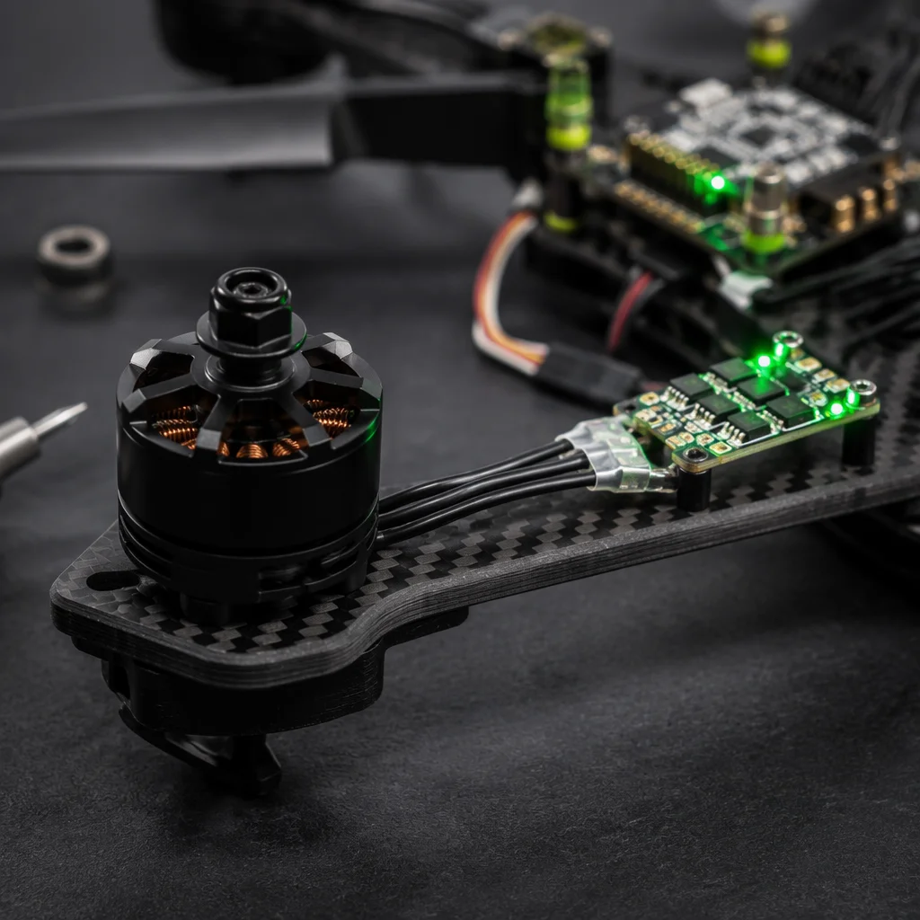
The motor selection for a logistics UAV starts not with a KV rating but with a thrust requirement at the mission AUW. The thrust required at hover is T = AUW × g / (η × N), where η is the propeller efficiency at hover (typically 0.55–0.65 for large props in static thrust) and N is the number of motors. For an 18 kg hexacopter with 65% propeller hover efficiency: T = (18 × 9.81) / (0.65 × 6) = 45.3 N per motor at hover. Adding a 30% margin for climb and wind — the minimum margin for delivery operations where a forced landing is not acceptable — the motor must deliver 58.9 N at 60–70% throttle on the operational voltage. This translates to a motor in the 80–120 KV range at 12S (44.4 V nominal), running 26–28 inch propellers with 6.0–7.5 inch pitch. Motors in this class — typically 6,000–8,000 W rated continuous power — deliver the hover thrust at approximately 55% of their continuous rating, providing thermal headroom for the climb and wind penetration phases of the mission.
The ESC selection is equally constrained. At 60 N of thrust per motor with 28-inch propellers at 12S, the motor draws approximately 40–55 A at hover. With six motors, the total hover current is 240–330 A — a load that demands ESCs with CAN FD or DShot 1200 protocol support for synchronized throttle response across all six motors. A 60 A-rated ESC running at 55 A hover current has no headroom for the transient current spikes during gust response, which can reach 80–90 A for 100–200 ms. The minimum ESC rating for a logistics hexacopter in this class is 80 A continuous per motor with 120 A burst capability for 10 seconds — a specification that eliminates most compact 4-in-1 ESC boards in favor of individual ESCs on the arms for thermal management. For the protocol-level constraints, the flight controller and ESC matching guide covers the CAN FD vs. DShot trade-off in multirotor configurations with six or more motors.
 Concept illustration
Battery and power: the endurance-payload trade-off
The battery system is where most logistics UAV designs fail the transition from concept to operation. A manufacturer's endurance specification of "55 minutes with 5 kg payload" typically assumes a brand-new battery at 25°C ambient temperature, zero wind, and sea-level air density. The same aircraft at 5°C with a battery that has completed 80 cycles, flying into a 3 m/s headwind at 500 m above sea level, achieves approximately 28–32 minutes of endurance — if the route requires 35 minutes, the aircraft does not complete the mission. Logistics UAV procurement must specify battery capacity for the worst-case combination of environmental and aging factors, not for the nominal test condition.
The energy consumption of a delivery drone follows a three-phase profile. The climb-out phase consumes 2.5–3.5× the hover power for 60–90 seconds as the aircraft accelerates to cruise speed and gains altitude. The cruise phase consumes approximately 0.85–1.0× the hover power at the optimal cruise speed (typically 12–16 m/s for a heavy-lift hexacopter, where translational lift reduces the power required by 10–15% compared to hover). The descent and landing phase consumes 0.5–0.7× the hover power. A 15 km delivery route with a 1-minute climb, 12-minute cruise at 14 m/s, and 2-minute descent and precision landing consumes approximately 250–320 Wh of energy from the battery, depending on headwind and payload mass.
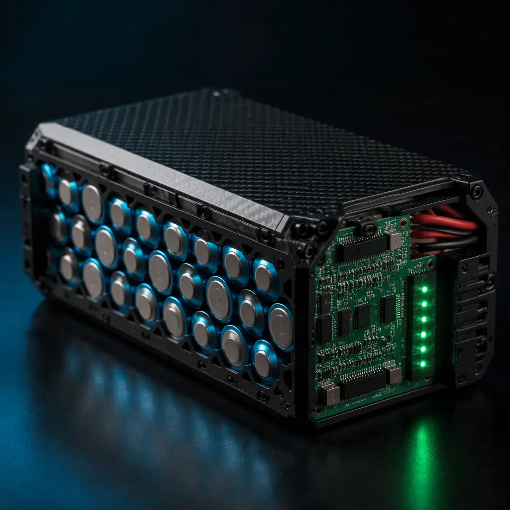
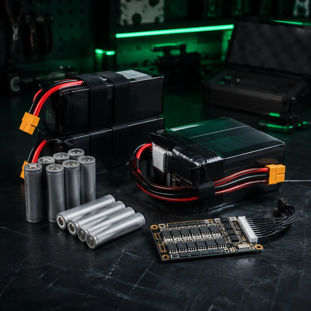
The cell selection for logistics UAV batteries favors 21700 Li-Ion cells (Samsung 50S, Molicel P45B) over LiPo pouches for two reasons. First, the energy density of 21700 Li-Ion cells at 260–270 Wh/kg is approximately 35–50% higher than high-discharge LiPo pouches at 170–190 Wh/kg — a difference that adds 8–15 minutes of endurance at the same battery mass. Second, cylindrical cells maintain their capacity through more charge-discharge cycles than pouches; a Samsung 50S cell retains 80% of its initial capacity after 500 cycles at 1C discharge, while a LiPo pouch at the same cycle count typically retains 65–70%. For a logistics operator planning 3–5 flights per day per aircraft, the cell-level cycle life determines whether the battery pack is replaced every 6 months or every 18 months. The cell configuration and BMS requirements for 12S packs are covered in detail in the UAV battery and power management guide.
 Concept illustration
Navigation and precision landing: redundancy for urban operations
A mapping drone that lands 5 meters from its intended landing point has inconvenienced the operator. A delivery drone that lands 5 meters from the delivery point has landed on a roof, in a tree, or on a road with moving vehicles. The navigation system for a logistics UAV must deliver landing precision of better than 1 meter CEP (circular error probable) in all weather conditions, and it must maintain that precision through a GNSS outage of at least 30 seconds — the duration of a typical urban canyon block where buildings obstruct satellite signals on one or both sides of the approach path.
The minimum navigation configuration for urban delivery is dual redundant GNSS receivers (L1/L2 multi-band, RTK-capable) with an IMU providing dead-reckoning through GNSS outages. The primary GNSS receiver provides the position solution; the secondary receiver provides a cross-check that detects position errors from multipath reflections or spoofing. When the two position solutions diverge by more than 2 meters, the flight controller flags a navigation integrity warning and initiates a hover-and-hold, giving the remote operator time to assess the situation. An IMU with gyro bias instability of ≤3°/hr maintains a dead-reckoning position error of less than 2 meters over a 30-second GNSS outage at 10 m/s — sufficient to navigate through a single urban block without GNSS before reacquiring satellites on the other side.
The landing sensor suite adds a third layer of precision. A downward-facing LiDAR rangefinder (typically 40–80 m range, ±2.5 cm accuracy) provides the altitude reference for the final 50 meters of descent, replacing barometric altitude which can drift by 5–10 meters due to ground-effect pressure changes near the landing surface. A downward-facing optical flow sensor or a simple RGB camera with AprilTag fiducial detection provides the horizontal position reference for the final 5 meters, correcting any GNSS drift accumulated during the approach. The payload delivery marker — a 50 cm × 50 cm high-contrast landing pad with a unique visual pattern — enables the optical system to lock onto the delivery point with sub-10 cm precision in the final meter of descent. For the RF link that enables remote monitoring during this phase, the UAV RF communication systems guide covers the telemetry and video downlink architecture for beyond visual line of sight operations.
Communications for BVLOS: redundancy across frequency bands
A logistics UAV operating beyond visual line of sight (BVLOS) at 10–20 km from the ground control station cannot rely on a single communication link. The C2 (command and control) link is safety-critical — loss of the C2 link triggers the flight controller's failsafe behavior, which in most configurations is a return-to-home at the current altitude, potentially climbing through controlled airspace on the return leg. A delivery operation with 15-minute route segments must maintain C2 link availability of >99.9% across the entire route, measured as the percentage of flight time with a valid C2 packet received within the link's timeout window (typically 1–2 seconds).
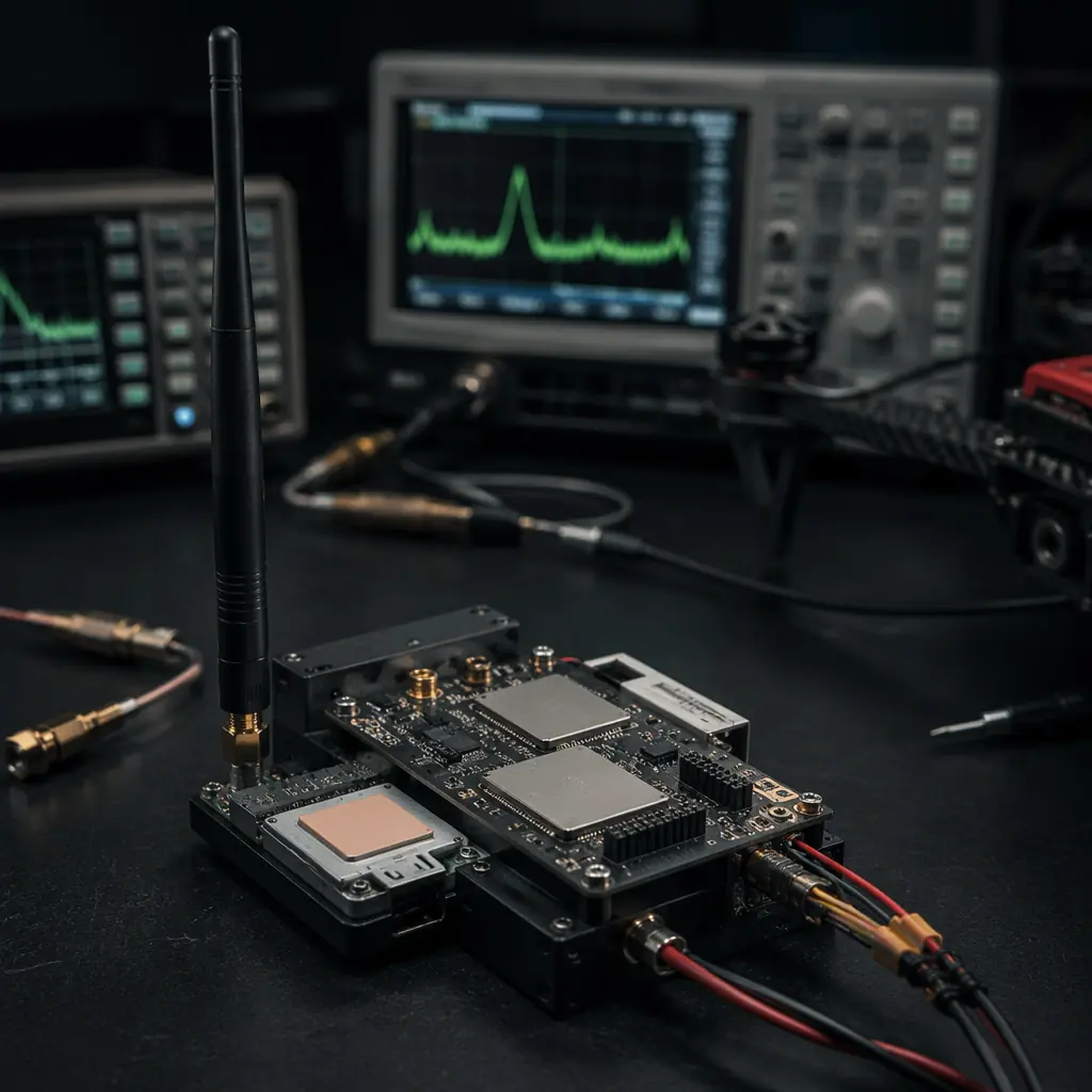
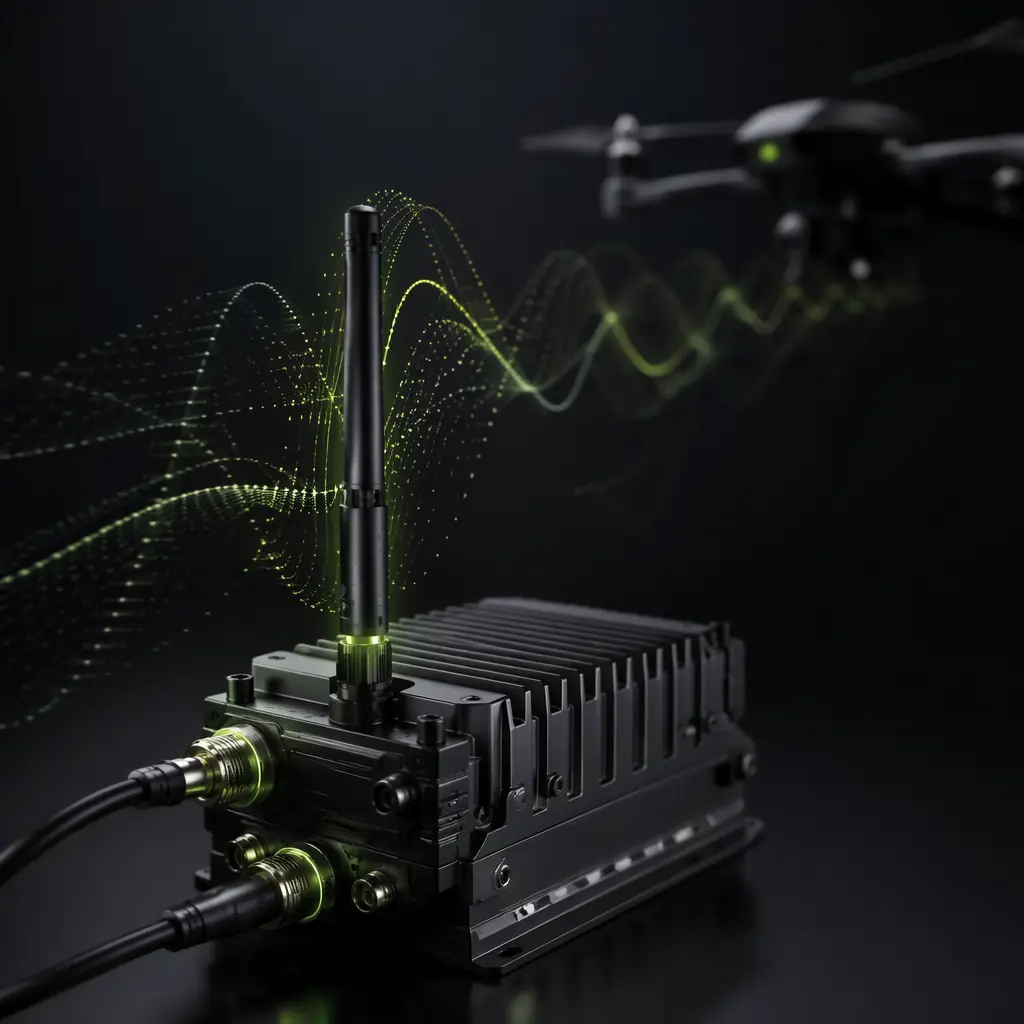
The C2 link architecture for BVLOS logistics uses dual-band redundancy: a primary link at 868/915 MHz for long-range telemetry (10–30 km range with 1 W transmit power and a high-gain ground antenna), and a secondary link over 4G/LTE cellular for areas within network coverage. The 868/915 MHz link uses the SiK or RFD900x protocol with frequency-hopping spread spectrum (FHSS), achieving a packet success rate of >99% at ranges up to 15 km in rural terrain and 8–12 km in suburban terrain with moderate RF interference. The 4G/LTE link provides higher bandwidth — enabling real-time video downlink for the operator to verify the delivery zone before initiating the descent — but is dependent on cellular coverage at the aircraft's altitude, which is not guaranteed at 120 m AGL where the aircraft is above the main lobe of most cell tower antennas.
The video downlink is a separate channel from the C2 link. A 1080p video feed with H.265 compression requires 2–4 Mbps of sustained throughput, which exceeds the capacity of an 868/915 MHz telemetry radio. The video downlink typically uses a 2.4 GHz or 5.8 GHz Wi-Fi-based link with a directional tracking antenna on the ground station — a setup that provides 5–15 km of video range with a 14 dBi patch antenna and automatic antenna tracking based on the aircraft's telemetry-reported position. When the video link drops below an acceptable bitrate, the operator can still monitor the aircraft's position, altitude and battery state over the 868 MHz C2 link and make the decision to continue or abort the mission based on telemetry alone. The antenna selection and link budget calculations for each frequency band are detailed in the RF systems guide.
 Concept illustration
Cargo airframe and payload release systems
The cargo integration on a delivery drone is not a mounting bracket — it is a structural subsystem that must maintain the payload's center of gravity within the aircraft's allowable CG envelope throughout the flight, protect the payload from vibration and impact during the release sequence, and release the payload without imparting a reaction force that destabilizes the aircraft in the final meter of descent. Each of these requirements drives specific component decisions.
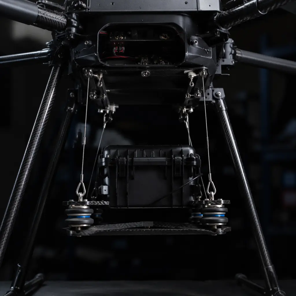
CG management and payload bay design. A logistics UAV's CG envelope — the range of CG positions within which the flight controller can maintain stable attitude control — is typically ±15–25 mm from the design CG in the longitudinal axis. A 5 kg payload whose CG shifts by 30 mm during flight — because the cargo shifts inside the bay, or because the release mechanism moves the payload from a stowed position to a release position — exceeds the CG envelope and degrades the flight controller's attitude authority. The payload bay must constrain the cargo rigidly in all three axes with mechanical stops, not friction, and the release mechanism must translate the payload downward without shifting it forward or aft. A four-point cable winch release system — two fore cables and two aft cables driven by a single drum with a differential pulley arrangement — lowers the payload straight down while maintaining its horizontal position relative to the aircraft.
Vibration isolation for sensitive cargo. Medical deliveries — blood products, vaccines, diagnostic samples — impose vibration limits on the payload environment. Whole blood transported with vibration exceeding 0.5 g RMS in the 20–500 Hz band shows measurable hemolysis (red blood cell rupture) after 15 minutes of exposure. A delivery drone's motor/propeller combination produces vibration at 80–200 Hz with amplitudes of 1–3 g at the motor mount, which attenuates to 0.3–0.8 g at the airframe center where the payload bay is mounted — above the hemolysis threshold. The payload bay suspension system must provide an additional 6–12 dB of vibration isolation between the airframe and the cargo, typically using wire rope isolators or tuned elastomer mounts selected for the combined mass of the payload bay, release mechanism and maximum cargo weight. For the structural stiffness considerations that affect vibration transmission, the UAV airframe materials guide covers the carbon fiber vs. aluminum trade-off for airframe components.
Release mechanism reliability. A cargo release mechanism that fails to release — the payload stays attached to the aircraft — forces the aircraft to land with the payload, requiring a landing zone large enough for the aircraft rather than a package-sized delivery point. A release mechanism that releases prematurely drops the payload at an unintended location, creating a safety hazard. The release mechanism must be fail-safe: a loss of power to the release actuator must result in the mechanism remaining locked (not releasing), and the actuator must require a deliberate command sequence — not a single PWM channel value — to initiate a release. An electromagnetic release with a mechanical latch that requires continuous power to hold the latch open and spring-force to close it on power loss provides this fail-safe behavior. The release sequence should require three conditions to be met before the actuator is energized: the aircraft must be below 5 meters AGL (verified by the LiDAR rangefinder), within 1 meter horizontally of the delivery point (verified by the optical landing sensor), and the operator must send an explicit release command over the C2 link. For the system integration approach, the UAV payload integration guide covers the electrical and mechanical interface standards.
 Concept illustration
Procurement checklist: 8 component decisions for logistics UAVs
These eight component decisions form the minimum validation gate before ordering hardware for a cargo delivery UAV. Each item is tied to a specific operational requirement — not a datasheet specification measured at nominal conditions, but a worst-case performance requirement derived from the mission profile.
1. Motor sizing at mission AUW with wind margin. Hover thrust per motor = (AUW × g) / (η × N) at the propeller efficiency for the selected diameter and pitch. Add 30% margin for climb and headwind penetration. Validate with a static thrust test at the mission battery voltage (not fully charged voltage): the motor must deliver the required thrust at ≤70% throttle. A motor that delivers the thrust only at >85% throttle has no headroom for gust response.
2. ESC continuous and burst current rating. Measure the hover current per motor with the actual propeller and battery combination. ESC continuous rating ≥1.3× hover current per motor. ESC burst rating (10 sec) ≥1.8× hover current per motor. A 60 A ESC running 55 A at hover with 90 A burst rating meets these margins. A 50 A ESC running 48 A at hover does not — the burst current during a 5 m/s gust climbs to 75 A, exceeding the 50 A ESC's burst capability and triggering over-current protection at the worst possible moment.
3. Battery capacity at worst-case environmental conditions. Calculate the total mission energy from a measured power curve — not from a manufacturer's endurance estimate — for the climb, cruise (with headwind) and descent phases. Add 20% reserve capacity for the return leg and landing in case of an aborted delivery. Add 15% derating for battery aging at 200 cycles. The resulting capacity, not the nominal capacity of a new battery at 25°C, determines whether the pack is adequate. For the 21700 cell selection methodology, see the battery management guide.
4. Dual GNSS with RTK and dead-reckoning IMU. Primary and secondary GNSS receivers, L1/L2 multi-band, RTK-capable with ≥10 Hz update rate. The IMU must have gyro bias instability ≤3°/hr for ≤2 m dead-reckoning drift over a 30-second GNSS outage. Validate by powering off the GNSS antennas during a hover test: the position estimate must remain within 2 meters of the true position (measured by a total station or laser tracker) for 30 seconds.
5. Dual-band C2 link with automatic failover. Primary link at 868/915 MHz with FHSS, ≥1 W transmit power, achieving packet success rate >99% at the maximum mission range. Secondary link over 4G/LTE with automatic failover within 500 ms of primary link loss. Validate with a ground test at the maximum mission range with the aircraft at altitude: the telemetry log must show zero C2 timeout events longer than 2 seconds.
6. Precision landing sensor suite. Downward LiDAR rangefinder (40–80 m range, ±2.5 cm accuracy) for altitude reference below 50 m AGL. Optical landing sensor with AprilTag or similar fiducial detection for horizontal positioning below 5 m AGL. Validate with an automated landing sequence onto a 50 cm × 50 cm delivery marker in 3 m/s wind: the landing point must be within 20 cm of the marker center across 10 consecutive landings.
7. Fail-safe payload release mechanism. Electromagnetic release with mechanical latch, fail-locked on power loss. Three-condition release interlock: altitude <5 m AGL, horizontal position within 1 m of delivery point, and explicit operator release command. Validate by testing the release mechanism 100 times with the maximum payload mass: zero premature releases and zero failures to release.
8. CG-constrained payload bay with vibration isolation. Payload bay rigidly constrains the cargo in all three axes with mechanical stops. Suspension system provides ≥10 dB vibration isolation at 80–200 Hz for the combined mass of the bay, release mechanism and maximum cargo. Validate with an accelerometer in the cargo position during a full-throttle sweep: vibration at the cargo must be ≤0.3 g RMS in the 20–500 Hz band for medical payloads, ≤1.0 g RMS for general cargo.
For teams evaluating whether to build a custom logistics platform from individual components or procure a pre-integrated delivery system, the cost-benefit analysis in the UAV component build vs. buy guide provides a structured decision framework across the three sourcing depths. For the regulatory certification pathway — CE marking for the European market, FCC for the US, and the specific requirements for BVLOS operations under EASA Specific Category and FAA Part 135 — the evaluation framework in the supplier evaluation checklist addresses the documentation and traceability requirements that accompany certified logistics UAV components.
Explore logistics solutions Back to Blog
Continue Reading
UAV Powertrain Matching
Motor KV, propeller selection and ESC sizing for heavy-lift hexacopter configurations.
Battery & Power Management
21700 Li-Ion pack configuration and BMS for mission-critical endurance.
UAV RF Communication Systems
Dual-band C2 link architecture for BVLOS operations at 10–30 km range.
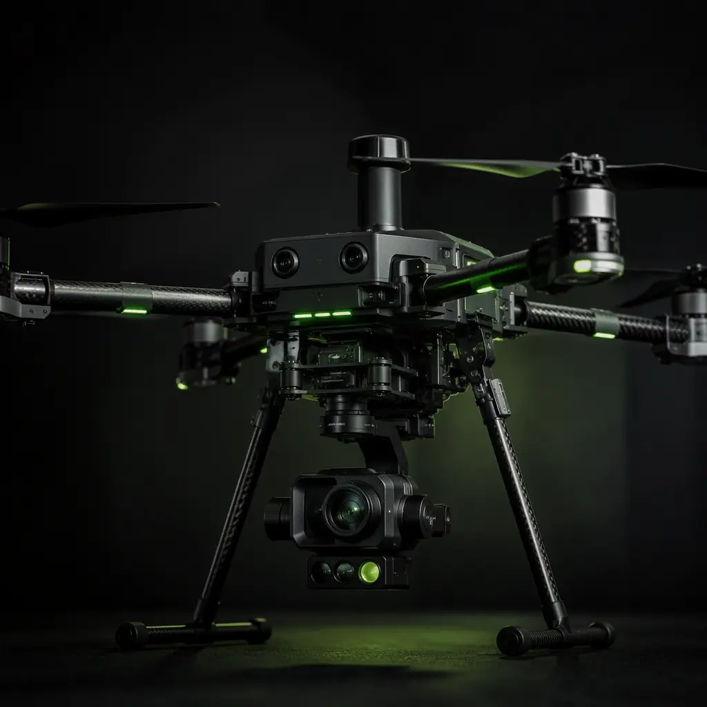
UAV Payload Integration Guide
Mechanical and electrical interface standards for cargo release and sensor payloads.
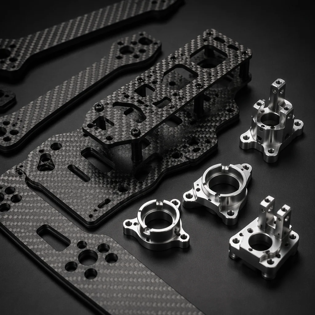
Airframe Materials Guide
Carbon fiber vs. aluminum structures for payload bay stiffness and vibration control.